Internal nasal dilator filter

Active Publication Date: 2005-12-06
BREATHEPURE HEALTHCARE L L C
View PDF36 Cites 51 Cited by
  • Summary
  • Abstract
  • Description
  • Claims
  • Application Information

AI Technical Summary

Benefits of technology

[0035]Overlaying the thin flexible band and adhesively attached to it and both semi-cylinders is a resilient member in its normal planar orientation. Internal dilation is provided by the effect of the resilient member which when bent from a planar surface applies outward biasing forces to the inside of the nose so that breathing is facilitated. The soft, gentle foam of the filter distributes the biasing forces and protects the inside of the nose from irritation.
[0036]The resilient member and adhesively attached foam is intended to be formed into a graceful “U” shape with the resil

Problems solved by technology

Millions of people suffer from nasal obstructions or physiological conditions that make nasal breathing difficult, uncomfortable, or impossible.
Any inflammation in this area causes swelling of the vascular tissue, narrowing down the nasal valve space and causing difficulty breathing.
However, they can have a deleterious effect after several days of use and may cause an increase in swelling.
However, if the nasal valve area is reduced due to mucusal swelling or because the outer wall tissue of the nasal passage draws in during inhalation, breathing through the nose becomes difficult creating a tendency to mouth breathe.
Breathing through the mouth bypasses the natural air handling system of the body thereby negating all the built-in physiological benefits.
However, surgical intervention is expensive, time consuming and may not entirely ameliorate the problem.
The adhesive must have enough strength to hold the dilator to the nose but not too much so that it is difficult or painful to remove.
Unfortunately, most have overlooked the advantages of coincident filtration.
Generally the devices proposed in the patents are suitable for their intended purposes but suffer from the significant disadvantage of no coincident filt

Method used


Image

  • Internal nasal dilator filter
  • Internal nasal dilator filter
  • Internal nasal dilator filter

Examples


Embodiment Construction

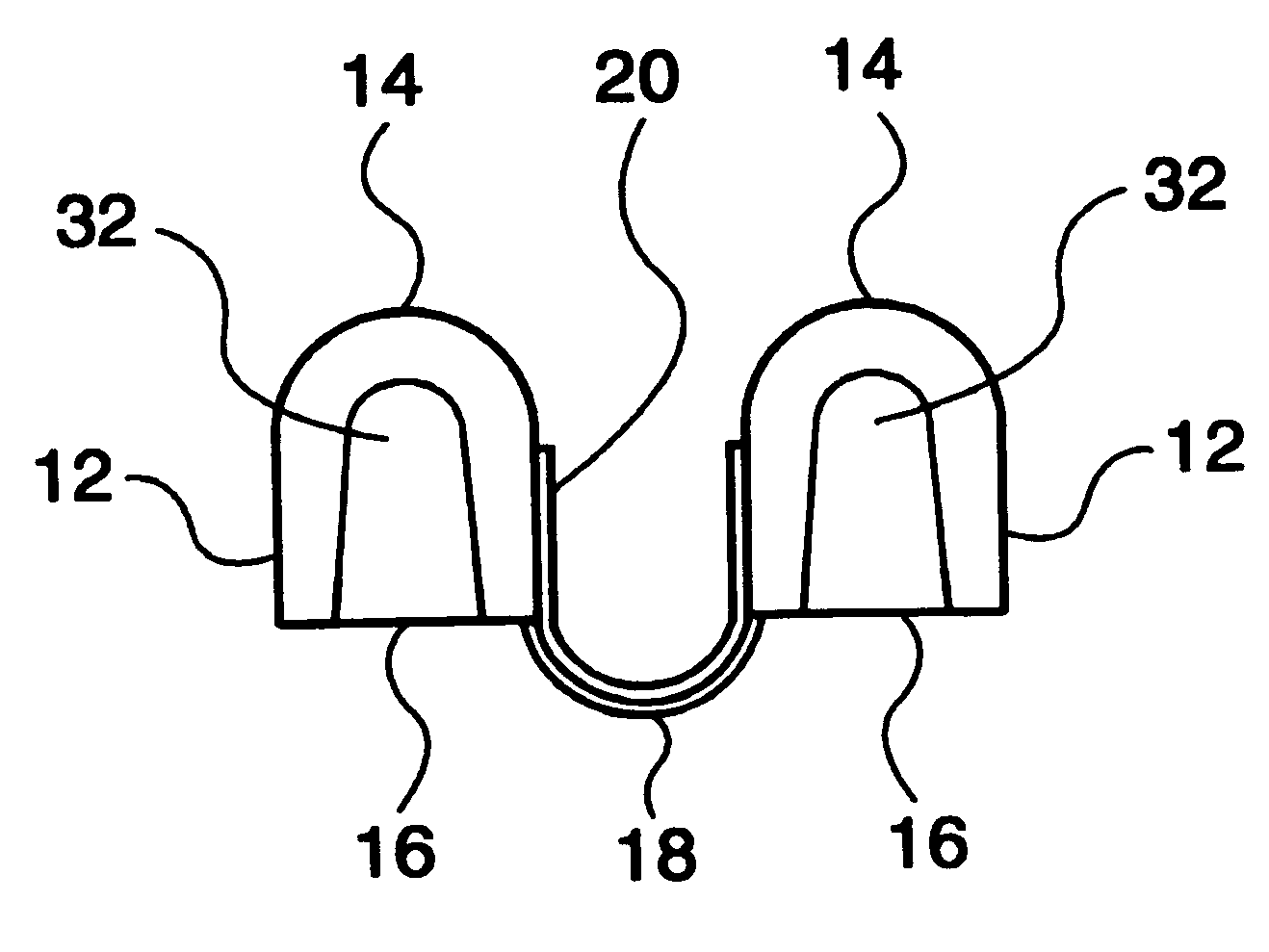
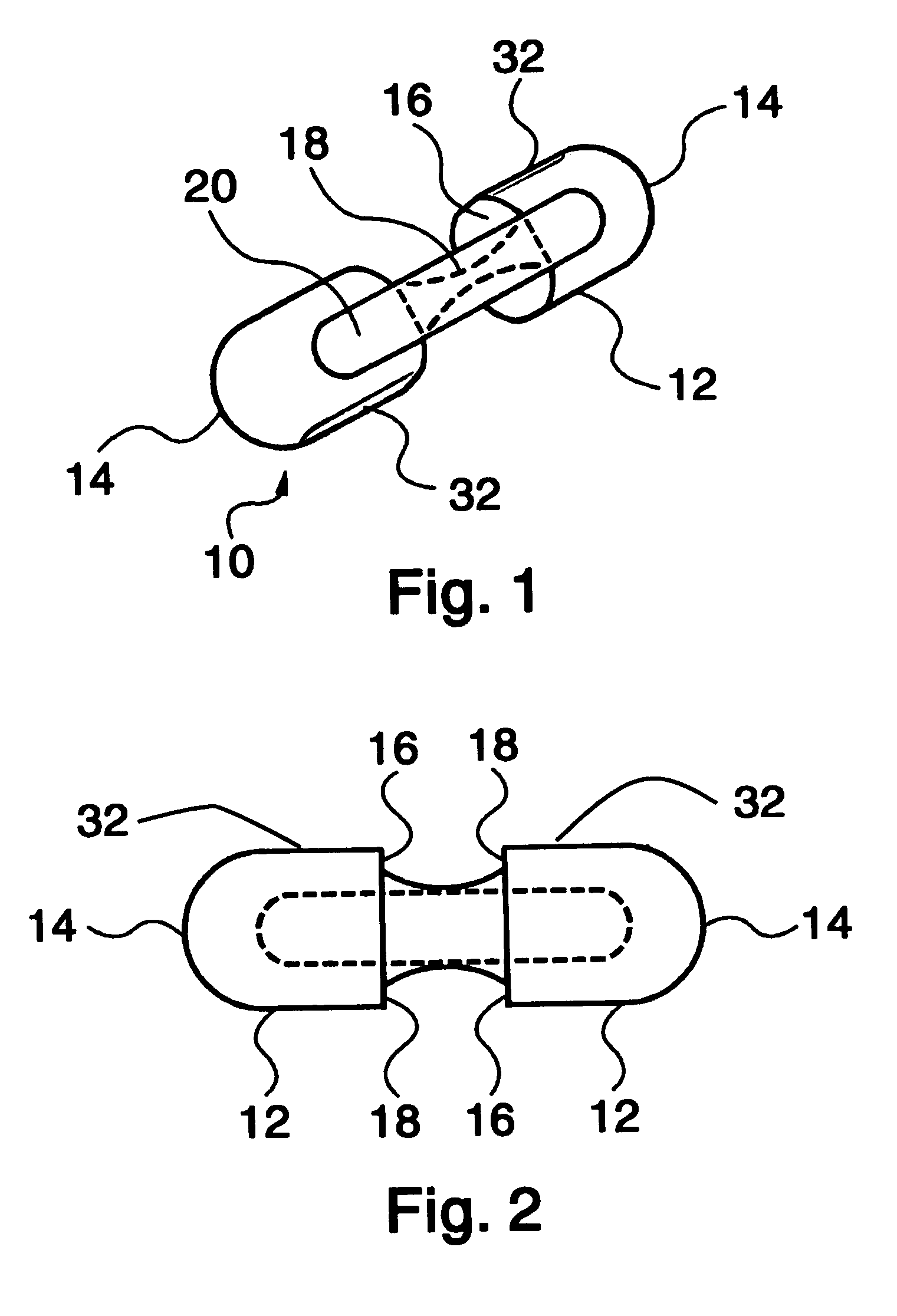
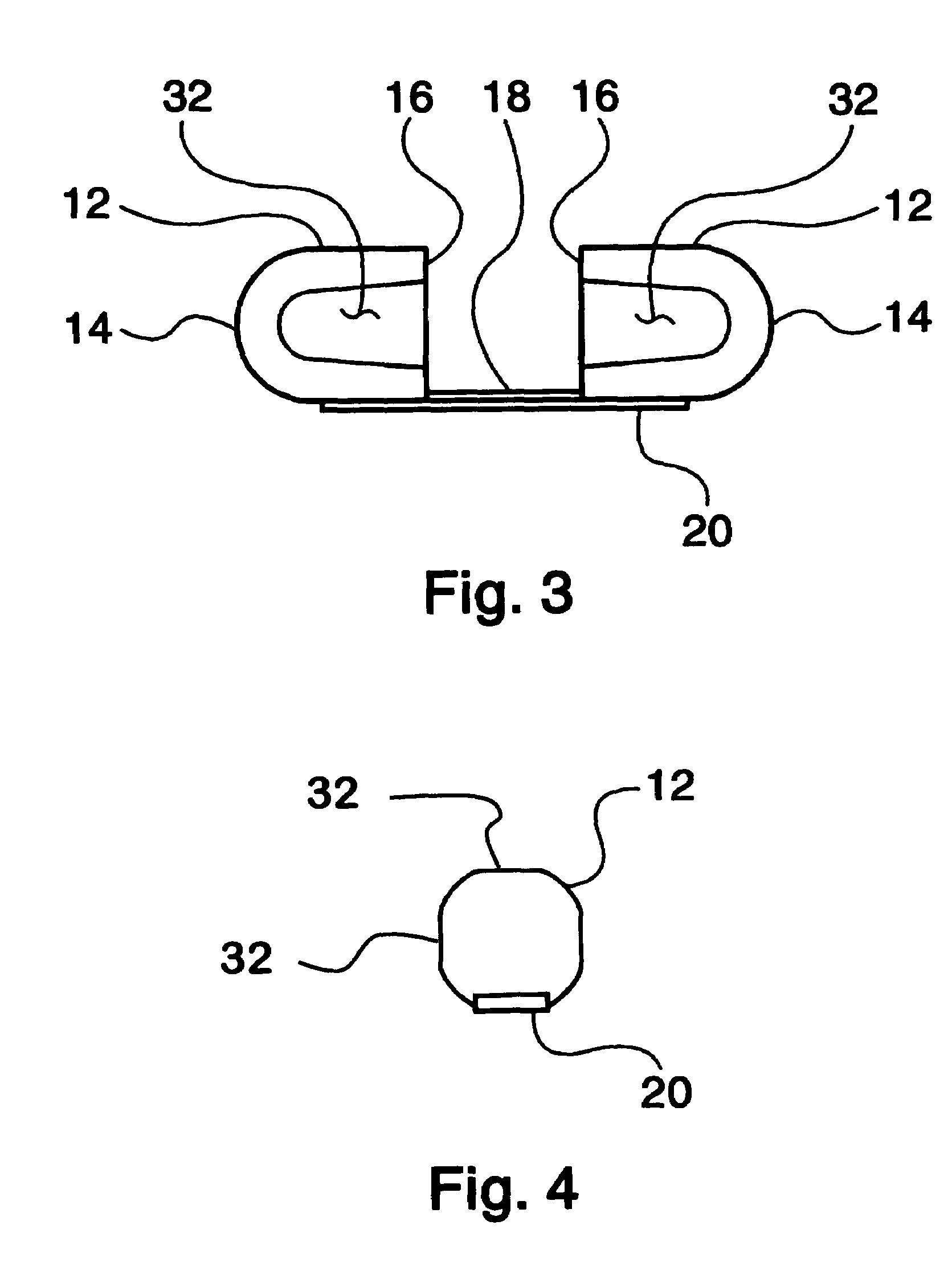
[0048]Referring to the drawings, FIG. 1 shows the assembly of the internal nasal dilator filter invention. The filter portion incorporates two semi-cylindrical shapes 12 of the same nominal diameter, which have at each distal end a spherical shape 14 to match and blend with the nominal semi-cylindrical diameter and at each other proximal end a base 16 with a flat surface whose plane is perpendicular to the cylinder axis. A thin, strong, flexible band 18 made of the same material as the semi-cylinders joins the semi-cylindrical shapes. The entire filter portion is made from the same material, reticulated foam of the polyurethane or silicone chemical family and of the polyether or polyester category. For the embodiments shown, the semi-cylindrical shapes and connecting flexible band are integrally molded, Referring again to FIG. 1, extending longitudinally along the thin, strong, flexible band 18 and further extending along a loft line of the circumferential surface of a portion of bo...


PUM


Abstract

A device combining internal nasal filtration and internal nasal dilation operating synchronously provides air filtration by retaining particulate in a single piece foam nasal filter during inhalation through the nose. Internal nasal dilation is provided by the effect of a resilient member adhesively affixed to the nasal foam filter and which when bent from a planar surface applies outward biasing forces to each nostril so that breathing is facilitated. The soft, gentle foam of the nasal filter distributes the biasing forces over a large area and protects the inside of the nose from irritation. An improved internal nasal dilator filter functions to provide increased air flow through dilation while removing various sizes of particulate through filtration.

Description

BACKGROUND OF THE INVENTION[0001]1. Field of the Invention[0002]This invention relates generally to the field of nasal dilators and air filtration and, more particularly, to an interal nasal dilator incorporating filtration having two semi-spherically topped substantially cylindrical reticulated foam depth filters with an integral interconnecting resilient member and arculate band set for insertion into the user's nostrils for nasal dilation and air filtration.[0003]2. Description of the Related Art[0004]Millions of people suffer from nasal obstructions or physiological conditions that make nasal breathing difficult, uncomfortable, or impossible. Examples of such conditions include narrowing of the nasal valve, allergic reactions, enlarged adenoid tissue and swollen nasal mucosa. The nasal valve, named by P.S. Mink in 1903 is the narrowest area in the nasal cavity, the adjacent area being larger both upstream and downstream. The nasal valve is located at the junction of the upper la...

Claims


Application Information

Patent Timeline
IPC IPC(8): A61F5/08A61M15/00A62B23/06
CPCA61F5/08A62B23/06
Inventor MICHAELS, ROBERT C.
Owner BREATHEPURE HEALTHCARE L L C
Why Eureka
Try Eureka