Moldable fabric

a fabric and fabric technology, applied in the field of moldable fabric, can solve the problems of only useful extending wells, high cost and time consumption, and inconvenient horizontally, and achieve the effect of expanding the width of the trailer bed

Inactive Publication Date: 2005-12-06
BATESVILLE SERVICES
View PDF71 Cites 26 Cited by
  • Summary
  • Abstract
  • Description
  • Claims
  • Application Information

AI Technical Summary

Benefits of technology

[0023]The mast may be pivotally mounted to the trailer bed for pivoting movement to and between an upright operable position and a lowered inoperable position. The mast may be mounted to a work platform and the work platform may be mounted to the trailer bed for movement transverse to a longitudinal axis of the trailer bed. The apparatus may further comprise a catwalk extending the length of the traile

Problems solved by technology

However, these vertically extending wells are only useful for removing oil and gas from the terminating downward end of the well.
Therefore, it is necessary to either make additional vertical drillings parallel and close to the first well, which is costly and time consuming, or to provide some means to extend the original well in a radial direction relative to the vertical longitudinal axis of the casing horizontally into the surrounding earth strata.
These horizontal drills have proved useful for extending the well horizontally but have proved to be relatively expensive.
Prototype testing of the device disclosed in U.S. Pat. Nos. 5,413,184 and 5,853,056 has proven less than satisfactory.
In particular, a number of problems plague the device disclosed in U.S. Pat. Nos. 5,413,184 and 5,853,056.
For example, the disclosed ball cutter is inefficient at best and ineffective at worst in cutting through the well casing.
The inherent spherical geometry of a ball cutter causes it “walk” or “chatter” during rotation as it attempts to bore through the well casing which greatly increases the amount of time required to bore through the casing.
Ball cutters are best utilized for deburring, and or cutting a radius in an existing hole or slot for example, and are simply not suitable for drilling holes.
Another problem is the torsional flexibility of the flexible shaft or flex cable.
Rather than transmitting rotational displacement to the ball cutter at 100% efficiency the flex cable tends to “wind up” or exhibit “backlash,” thus reducing the already inefficient cutting efficiency of the ball cutter even more.
Yet another problem is the tendency of the elbow to back away from the hole in the casing during drilling with the ball cutter.
Such backing away causes the elbow outlet to become misaligned with the hole in the casing thereby preventing smooth introduction of the nozzle and flexible tube into the hole in the casing.
Still another problem is the large amount of torsional friction generated between the elbow passageway and the flex cable which of course increases the horsepower requirements of the motor required to rotate the flex cable.
The addition of balls, separated by springs, to the flex cable, in an effort to alleviate the resistance of the apparatus to being rotated, has not remedied this problem.
A further problem is the closed nature of the apparatus of U.S. Pat. Nos. 5,413,184 and 5,853,056, which prevents its being taken apart, inspected, cleaned and repaired as needed.
For example, the invention of U.S. Pat. Nos. 5,413,184 and 5,853,056 is inefficient and time consuming to operate in that after the cutting tool has bored through the well casing the drilling operation must be interrupted so that the entire drilling apparatus can be retrieved to the earth surface in order to remove the well casing cutting tool and to install the earth strata boring grater nozzle.

Method used


Image

  • Moldable fabric
  • Moldable fabric
  • Moldable fabric

Examples


Embodiment Construction

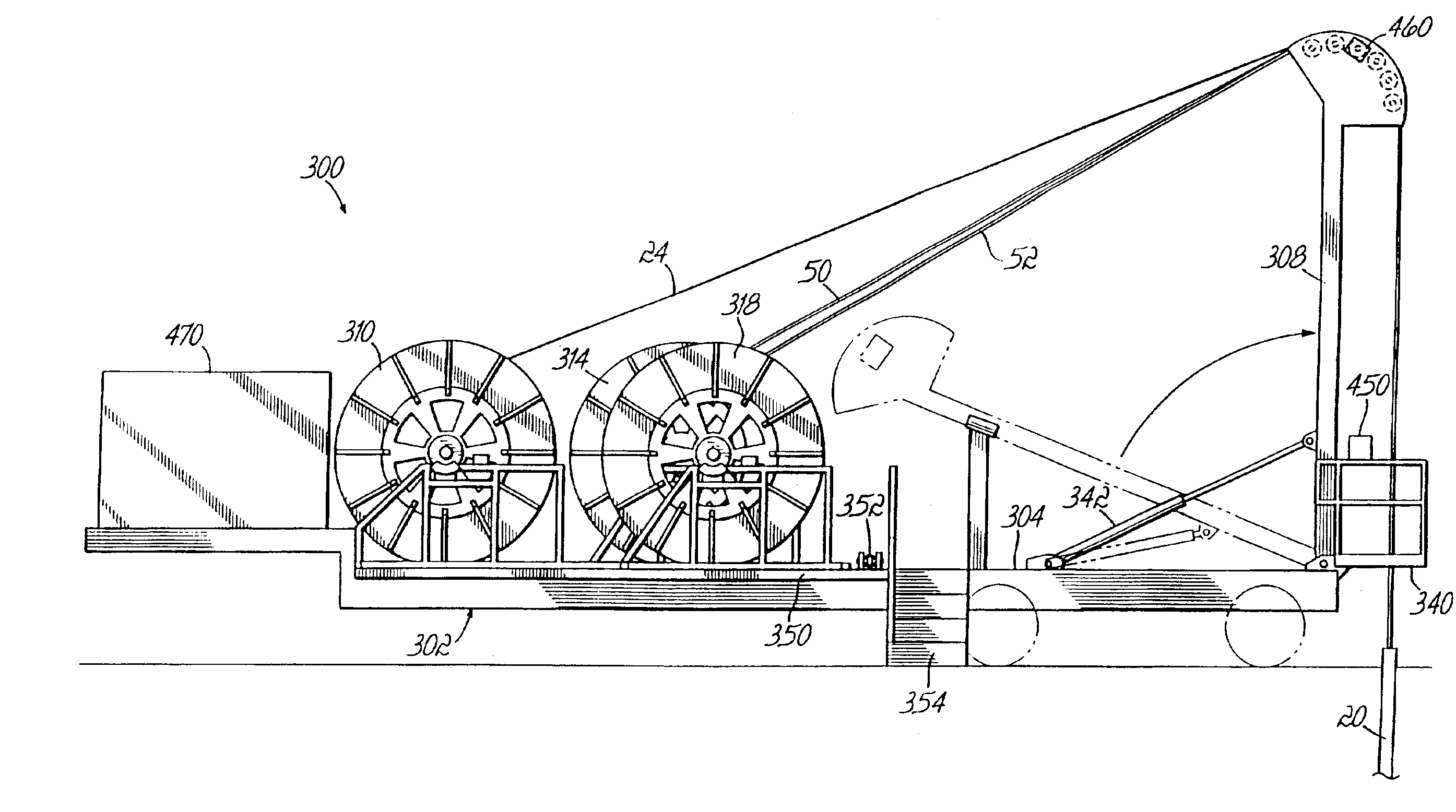
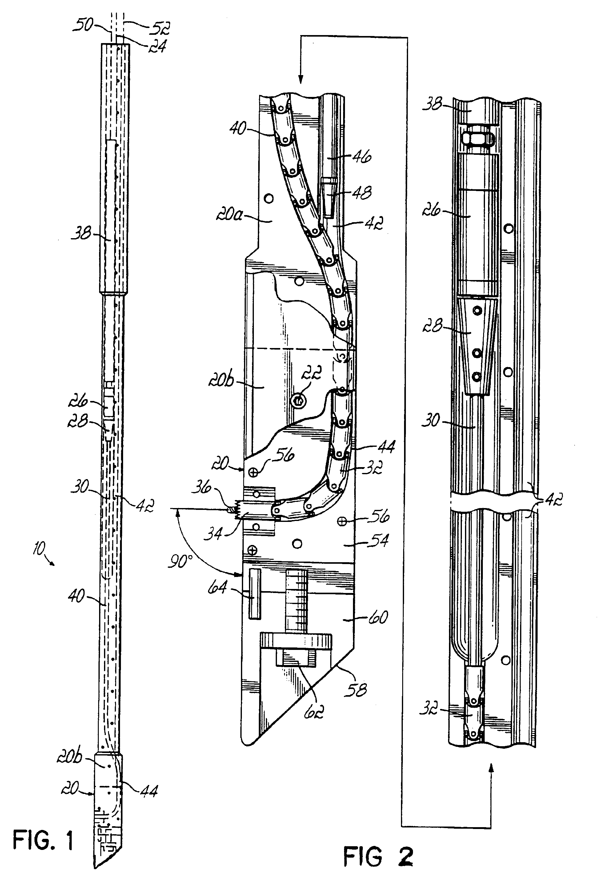
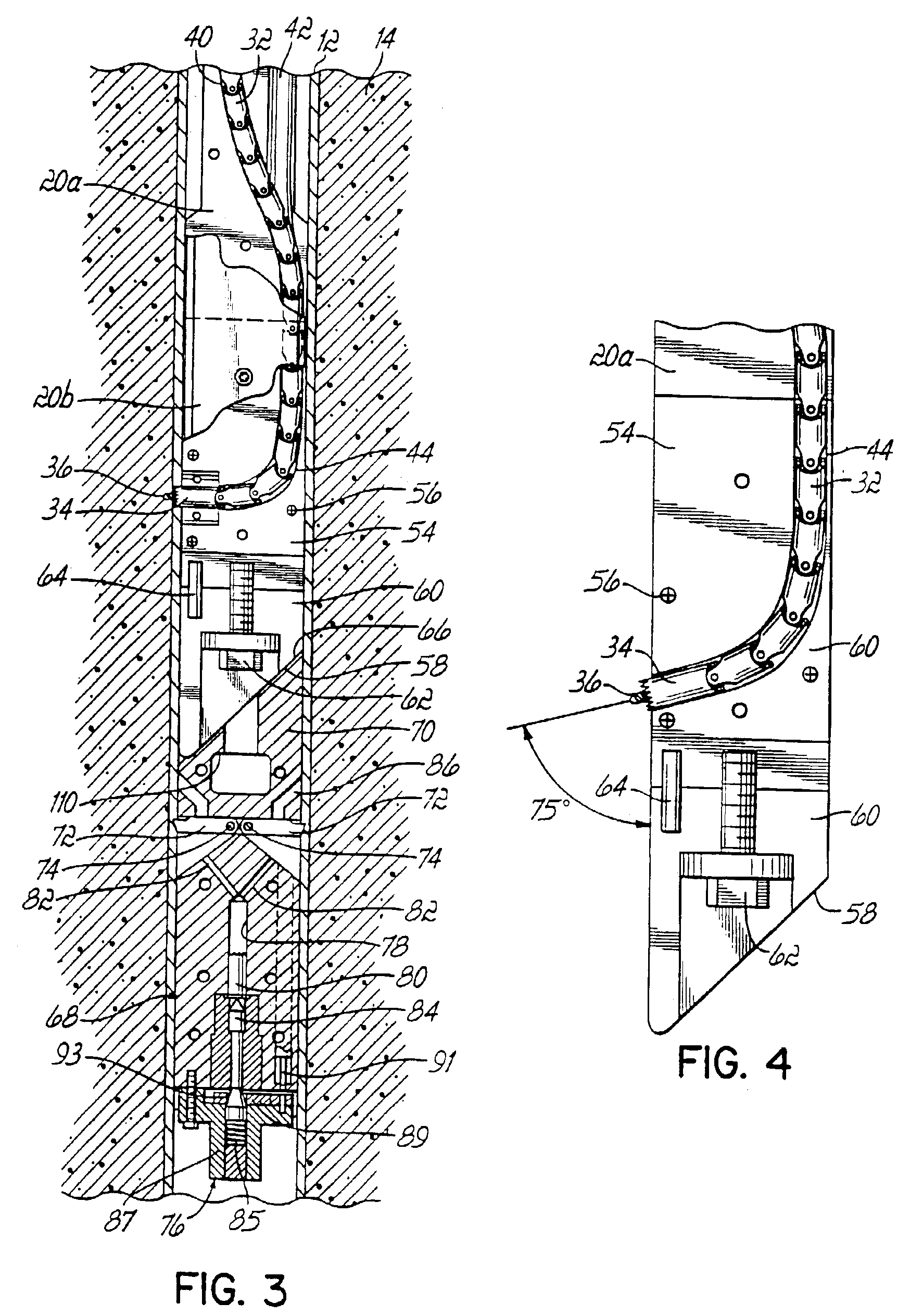
[0036]Referring first to FIG. 1 a boring apparatus 10 according to the principles of the present invention is illustrated. During use apparatus 10 is positionable inside a well casing 12 in the earth strata 14 (FIG. 3). The boring apparatus 10 includes a hollow carbon steel drill shoe 20. Drill shoe 20 has a longitudinal axis which, when inserted into casing 12, is generally parallel to a longitudinal axis of the well casing 12. Drill shoe 20 may preferably be fabricated in halves 20a, 20b securable together via bolts 22. Drill shoe 20 may be connected to a ½ inch diameter 6×25 IWRC wire rope 24 which is utilized to lower drill shoe 20 down into casing 12.

[0037]A fluid motor 26 imparts rotation to a motor coupling 28 which is connected to a drill bit shaft 30 itself connected to a plurality of interconnected universal joints 32 which terminate in a hole saw 34 with central pilot hole drill bit 36. Above motor 26 is a motor locator 38; motor locator 38 and drill shoe 20 include coope...


PUM


Abstract

Apparatus for boring a hole from an inside of a casing outwardly at an angle relative to a longitudinal axis of the casing comprises a drill shoe having a longitudinal axis and being positionable in the casing, the shoe having first and second passageways which converge into a third passageway exiting the shoe, a torsional load transmitting element and a cutting element connecting to one end of the torsional load transmitting element, the torsional load transmitting element and cutting element being positioned in the first passageway during non-use and in the third passageway during use, and a fluid conduit and a nozzle connected to one end of the fluid conduit, the fluid conduit and nozzle being positioned in the second passageway during non-use and in the third passageway during use.

Description

RELATED APPLICATIONS[0001]This application claims priority to provisional application Ser. No. 69 / 388,004 filed Jun. 12, 2002 for a Moldable Brassiere Fabric, which is a divisional of Ser. No. 10 / 147,766 filed May 16, 2002 now U.S. Pat. 6,588,517, which is a divisional of Ser. No. 09 / 761,985 filed Jan. 17, 2001 now U.S. Pat. 6,412,578, which is a continuation-in-part of Ser. No. 09 / 643,306 filed Aug. 21, 2000 now U.S. Pat. 6,378,629, incorporated herein by reference.FIELD OF THE INVENTION[0002]This invention relates broadly to the boring of a hole through the wall of a tube from the inside of the tube outwardly at an angle to a longitudinal axis of the tube. More specifically, this invention relates to apparatus for drilling through an oil or gas well casing at an angle to the longitudinal axis of the casing and into the earth strata surrounding the well casing. More particularly, this invention relates to an improved such drilling apparatus and to a means of transporting, deploying...

Claims


Application Information

Patent Timeline
IPC IPC(8): E21B7/06E21B7/08E21B17/20E21B23/01
CPCE21B7/061E21B17/20E21B23/01
Inventor BAIRD, BILLY CARR
Owner BATESVILLE SERVICES
Why Eureka
Try Eureka