Fuel cell system

a fuel cell and system technology, applied in the field of fuel cell systems, can solve the problems of reducing the power affecting the production efficiency of the system, and affecting the service/maintenance of the secondary cell, so as to achieve the effect of rugged and reliable, and reducing the internal resistan

Inactive Publication Date: 2005-12-06
DAIMLER AG
View PDF11 Cites 11 Cited by
  • Summary
  • Abstract
  • Description
  • Claims
  • Application Information

AI Technical Summary

Benefits of technology

[0007]It is, therefore, an object of the present invention to devise a fuel-cell system, as well as a method for operating such a fuel-cell system, which will avoid the above-mentioned related-art disadvantages and which will constitute a cost-effective, rugged and reliable system.
[0008]The present invention provides a fuel-cell system comprising devices for supplying the operating agents for a fuel cell and comprising an electrical energy accumulator, wherein the energy accumulator (5) has a battery (6) and an intermediate charge store (7) having a lower internal resistance (R1,LZS) than the internal resistance (Ri,BAT) of the battery (6), a switch (9) being provided in the electrical connection between the energy accumulator (5) and the fuel cell (2).
[0009]Such an energy accumulator design, composed of a battery and an intermediate charge store having a substantially lower internal resistance than that of the battery, and the use of a switch between the energy accumulator and the fuel cell, makes it possible to operate a fuel-cell system of this kind with an excellent power efficiency, while entailing a minimum number of components.
[0010]The switch enables the fuel-cell system to be activated or deactivated depending on the fuel cell's available power output. Should the situation arise that the fuel cell is not able to provide the necessary power, then the switch is opened and the connected electrical loads draw their power directly from the battery. When the fuel cell has recovered, the switch may be closed and the comparatively high current that sets in is, for the most part, stored temporarily in the intermediate charge store, and only a comparatively small portion attains the battery and charges the same. In this context, the loads are able to continue to draw the required electrical power from the area of the battery. If, at this point, the switch is opened again because the fuel cell is again operating in a critical region of its curve, the battery may then continue to be recharged by the charge intermediately stored in the intermediate charge store, while the fuel cell that is decoupled from the system is able to recover again.
[0011]Through continuous actuation of the switch in a suitable rhythm, for example in dependence upon the preset limiting voltages, as provided by one particularly beneficial exemplary embodiment of the method according to the present invention, the system voltage is able to be retained within a voltage range or voltage window, thus, in practical limits, kept virtually constant.
[0012]The present invention also provides a method for operating a fuel-cell system, wherein, to charge the energy accumulator (5), a system voltage (U0) of the fuel-cell system (1) is regulated such that, in response to an opening or closing of the switch (9) between the fuel cell (2) and the energy accumulator (5), the system voltage (U0) is kept constant within a predefined voltage range.

Problems solved by technology

However, this operating point is often not desired, since such high currents are not necessary for charging the battery, or because the fuel cell is not being used under optimal operating conditions.
As a result, the power efficiency of the system is degraded due to the comparatively high internal resistance of the battery and the unfavorable operating conditions of the fuel cell.
However, the design utilizing the DC / DC converter constitutes a serious disadvantage in the series production of such systems, for example when they are intended for use in motor vehicles.
DC / DC converters of this kind are frequently prone to failure, require a relatively large installation space and, in particular, are very expensive, so that the installation, on the whole, is made substantially more expensive.
This has serious disadvantageous effects on the economic efficiency of such systems in the above application case of fuel-cell systems in a motor vehicle, because of the comparatively high piece numbers to be expected.

Method used


Image

  • Fuel cell system
  • Fuel cell system
  • Fuel cell system

Examples


Embodiment Construction

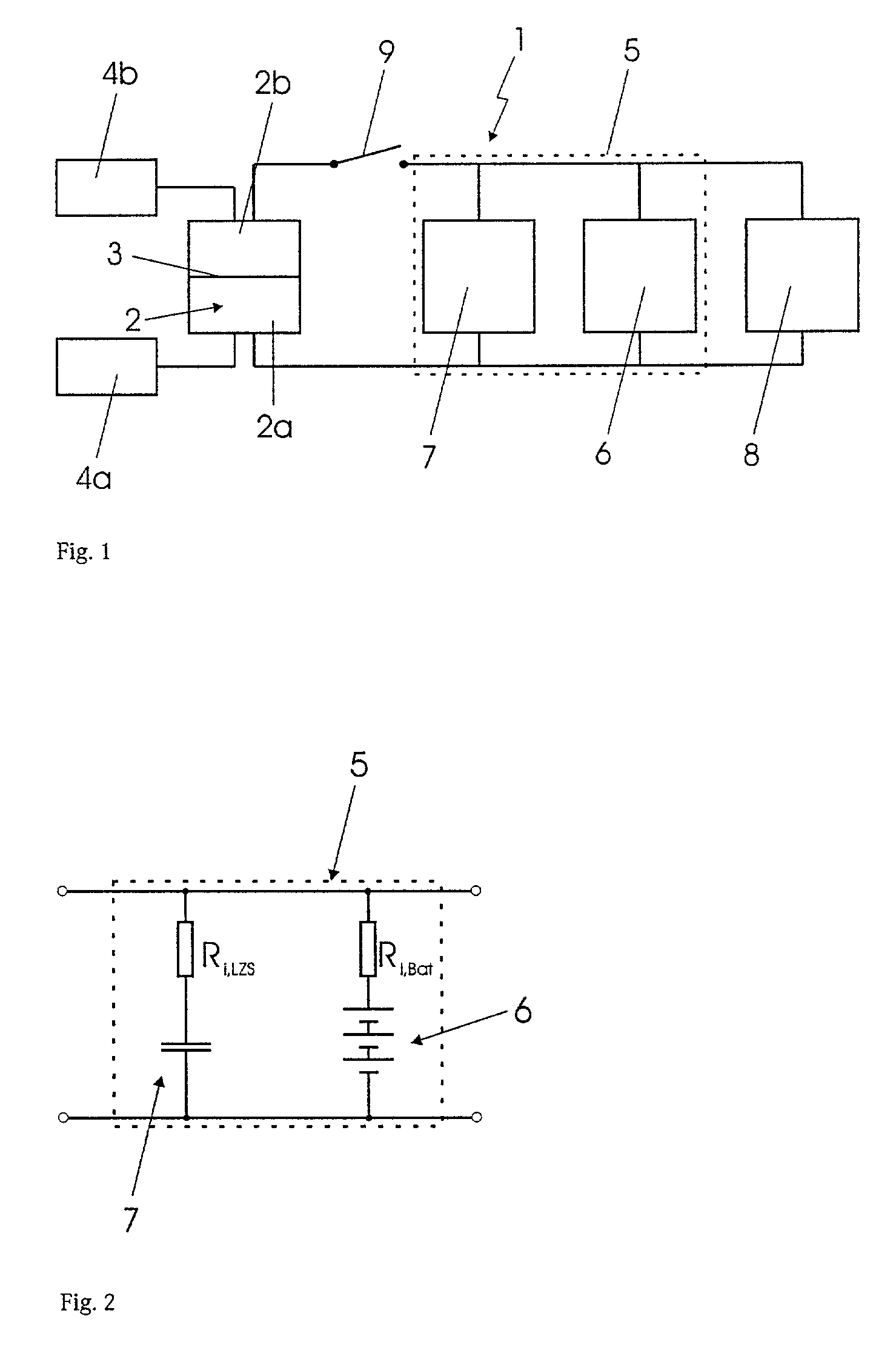
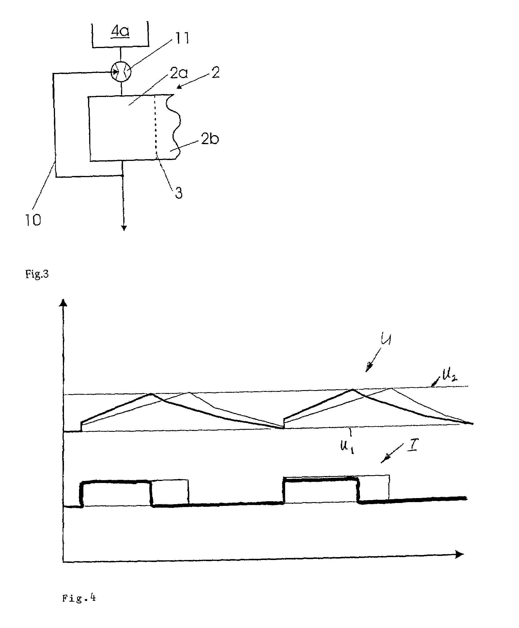
[0021]FIG. 1 illustrates the underlying principle of the design of a fuel-cell system 1 according to the present invention. Fuel-cell system 1 has a fuel cell 2, including an anode region 2a and a cathode region 2b. Here, anode region 2a of fuel cell 2 is separated by a proton-exchange membrane 3 (PEM) from cathode region 2b of fuel cell 2. Besides being a single cell, fuel cell 2 is defined to include a fuel-cell stack as well. In addition to PEM fuel cell 2 selected for the exemplary embodiment, many other types of fuel cells 2 are, of course, also conceivable in connection with the designs described here, such as phosphoric acid fuel cells, direct methanol fuel cells, or the like.

[0022]Anode region 2a is coupled via a device 4a for supplying fuel cell 2 with operating agents, here, in particular, a gas-generating system 4a, through which anode region 2a of fuel cell 2 is able to be supplied with the operating agent it requires, in the context of a PEM fuel cell, generally with hy...


PUM

PropertyMeasurementUnit
internal resistance Riaaaaaaaaaa
voltageaaaaaaaaaa

Abstract

A fuel-cell system, in particular for a vehicle, has a device for supplying the operating agents for a fuel cell and an electrical energy accumulator. The energy accumulator is composed of a battery and of an intermediate charge store which has a lower internal resistance than the battery. A switch is provided in the electrical connection between the energy accumulator and the fuel cell.

Description

[0001]Priority to German Patent Application No. DE 101 25 106.8-45, filed May 23, 2001 and incorporated hereby by reference herein, is claimed.BACKGROUND INFORMATION[0002]The present invention is directed to a fuel-cell system with an energy accumulator, as well as to a method for operating such a fuel-cell system.[0003]A fuel-cell system is disclosed in European Patent Application No. 0 782 209 A1. This fuel-cell system has a battery to enable the fuel cell, which depending on the particular system is relatively sluggish, to be used in systems having very high dynamic power-supply requirements.[0004]Generally, when the fuel cells and the battery are coupled, due to the existing curves of the fuel cell and the comparatively stiff curve of the battery, an operating point corresponding to the point of intersection of these curves sets in. However, this operating point is often not desired, since such high currents are not necessary for charging the battery, or because the fuel cell is...

Claims


Application Information

Patent Timeline
Patent Type & Authority Patents(United States)
IPC IPC(8): H01M8/04082H01M8/04089H01M8/0438H01M8/04537H01M8/04746H01M8/04858H01M8/04955H01M16/00
CPCH01M8/04097H01M8/04626H01M8/04865H01M8/0491H01M8/04955H01M16/006H01M8/04201H01M8/04388H01M8/04753H01M2250/20Y02T90/32Y10S204/04Y02E60/50Y02T90/40Y02E60/10
Inventor AUTENRIETH, RAINERGERBERICH, ROBERTKONRAD, GERHARDLEDWIG, KARSTENNIEHUES, MICHAELWALTER, MARKUS
Owner DAIMLER AG
Why Eureka
Try Eureka