

Sense amplifier having synchronous reset or asynchronous reset capability
- Summary
- Abstract
- Description
- Claims
- Application Information
AI Technical Summary
Benefits of technology
Problems solved by technology
Method used
Image

Examples
first embodiment
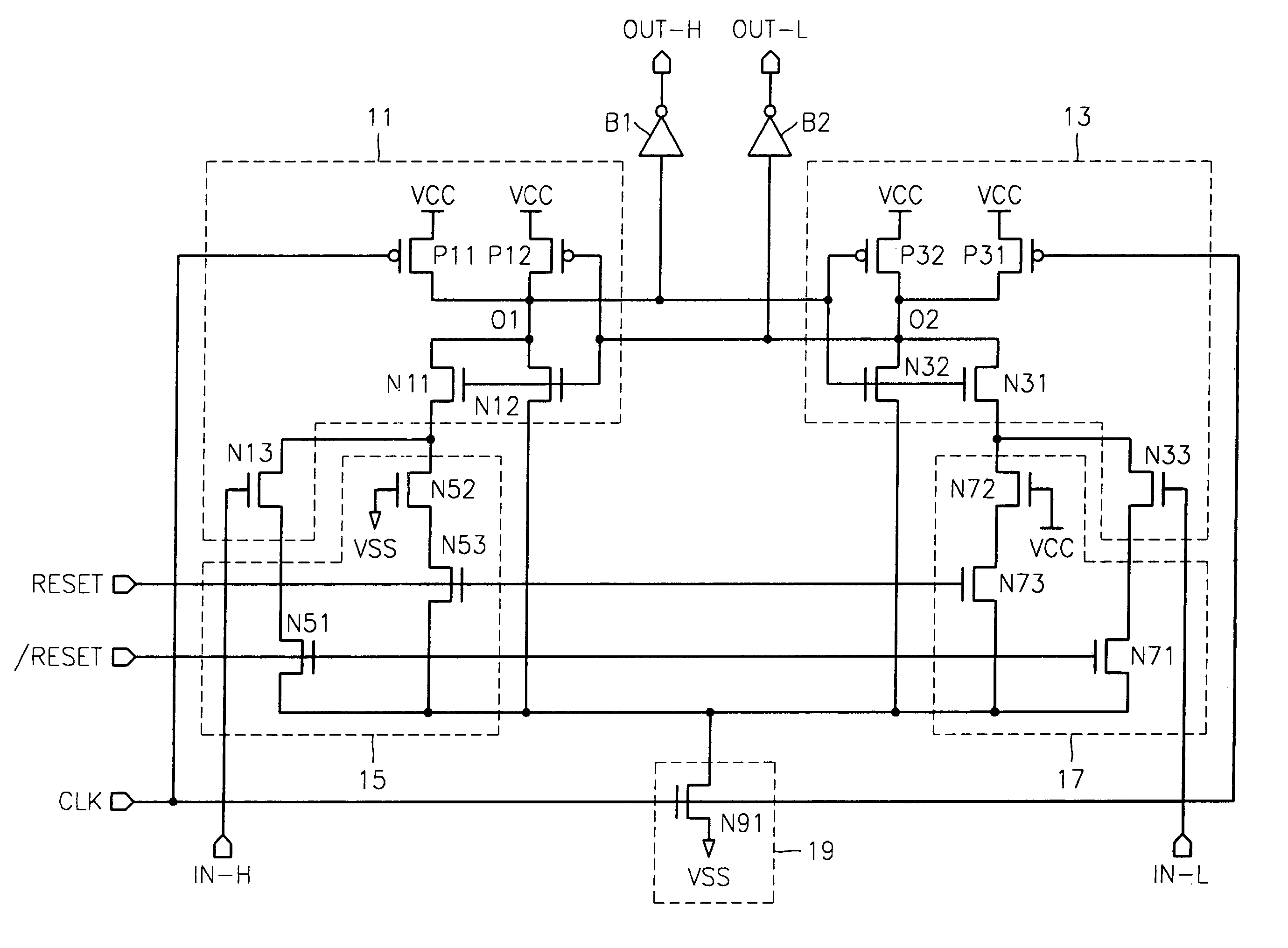
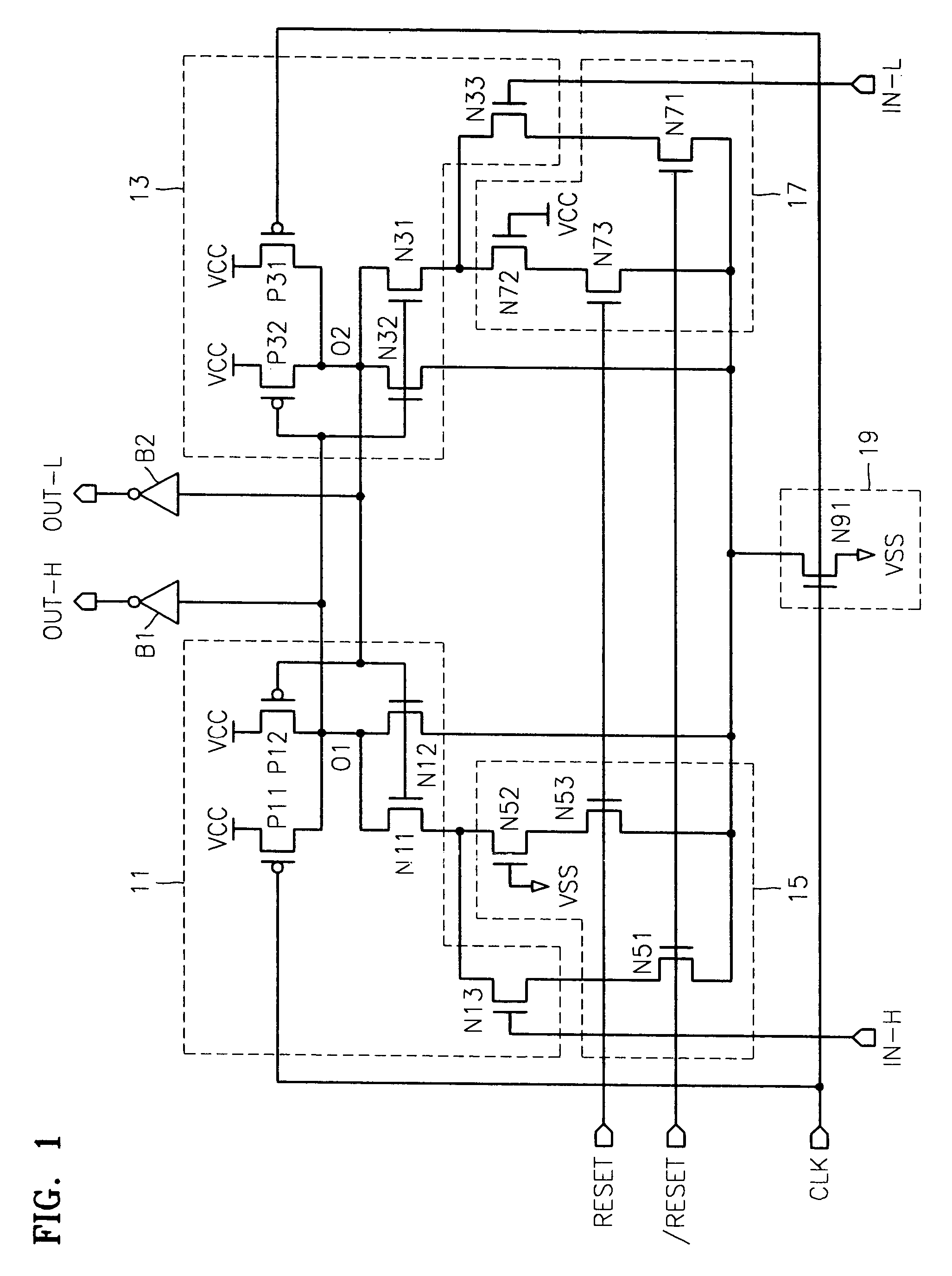
[0036]The operation of the sense amplifier having the synchronous reset capability according to the present invention shown in FIG. 1 will be described in greater detail.
[0037]When the reset signal RESET is disabled to logic “low”, the NMOS transistor N53 of the first controller 15 and the NMOS transistor N73 of the second controller 17 are turned off, and the NMOS transistor N51 of the first controller 15 and the NMOS transistor N71 of the second controller 17 are turned on. Thus, the sense amplifier performs a normal operation, sense-amplifies the input signal IN-H and the complementary input signal IN-L in response to the clock signal CLK, and generates the final output signal OUT-H and the complementary output signal OUT-L.
[0038]When the reset signal RESET is enabled to logic “high”, the NMOS transistor N53 of the first controller 15 and the NMOS transistor N73 of the second controller 17 are turned on, and the NMOS transistor N51 of the first controller 15 and the NMOS transist...
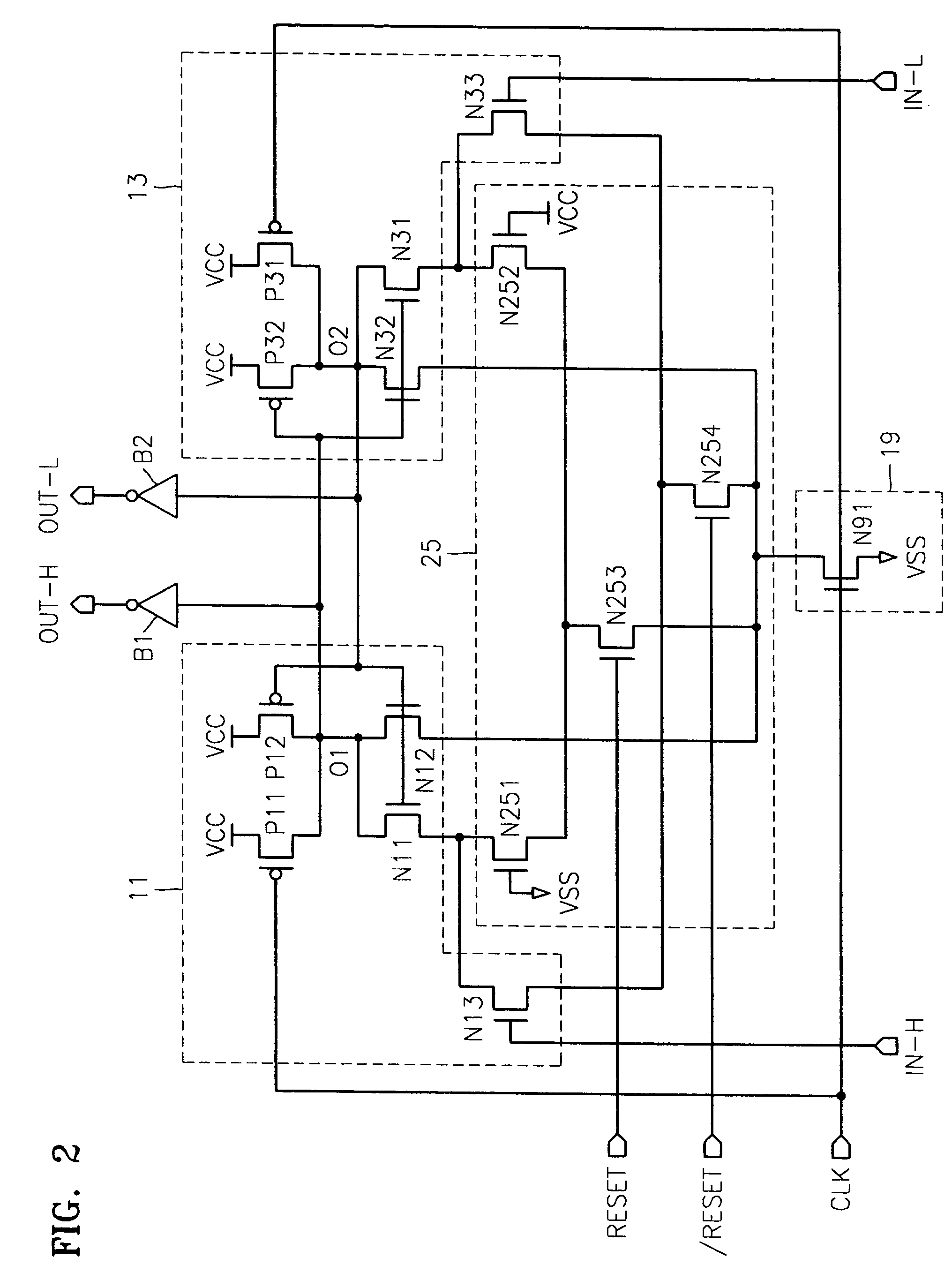
second embodiment
[0044]The operation of the sense amplifier having the synchronous reset capability according to the present invention is the same as that shown in FIG. 1. That is, when the reset signal RESET is enabled to logic “high”, the NMOS transistor N253 of the controller 25 is turned on, and the NMOS transistor N254 of the controller 25 is turned off. Thus, the sense amplifier does not receive the input signal IN-H and the complementary input signal IN-L, and values of the final output signal OUT-H and the complementary output signal OUT-L are determined by a value predetermined by the NMOS transistor N251 of the controller 25 and a value predetermined by the NMOS transistor N252 of the controller 25, respectively. That is, the ground voltage VSS is applied to the gate of the NMOS transistor N251, and thus the NMOS transistor N251 is turned off, and the power supply voltage VCC is applied to the gate of the NMOS transistor N252, and thus the NMOS transistor N252 is turned on. In this state, ...
PUM
 Abstract
Description
Claims
Application Information