Beam-splitter optics design that maintains an unflipped (unmirrored) image for a catadioptric lithographic system

Inactive Publication Date: 2005-12-06
ASML HLDG NV
View PDF9 Cites 4 Cited by
  • Summary
  • Abstract
  • Description
  • Claims
  • Application Information

AI Technical Summary

Benefits of technology

[0012]In another embodiment of the present invention, the beam-splitter cube includes two optical prism halves separated by a spacer plate. The width of the spacer plate is a variable in an offset created between the image axis of the object plane beam and the wafer plane beam. The object plane beam passes from the object plane through the reticle group of optics. The wafer plane beam passes through the wafer group. The width of the spacer plate depends on the amount of desired offset between the image axis of the object plane beam and the wafer plane beam. The width can be zero (in other words, optical surfaces of the two optical prism halves are in optical contact) in one embodiment or can vary in alternative embodiments. The width of the spacer plate determines the amount of background scattered light that is incident on the baffle plate and the wafer group. The spacer plate can be manufa

Problems solved by technology

The use of mirrors, however, c

Method used


Image

  • Beam-splitter optics design that maintains an unflipped (unmirrored) image for a catadioptric lithographic system
  • Beam-splitter optics design that maintains an unflipped (unmirrored) image for a catadioptric lithographic system
  • Beam-splitter optics design that maintains an unflipped (unmirrored) image for a catadioptric lithographic system

Examples


Embodiment Construction

Table of Contents

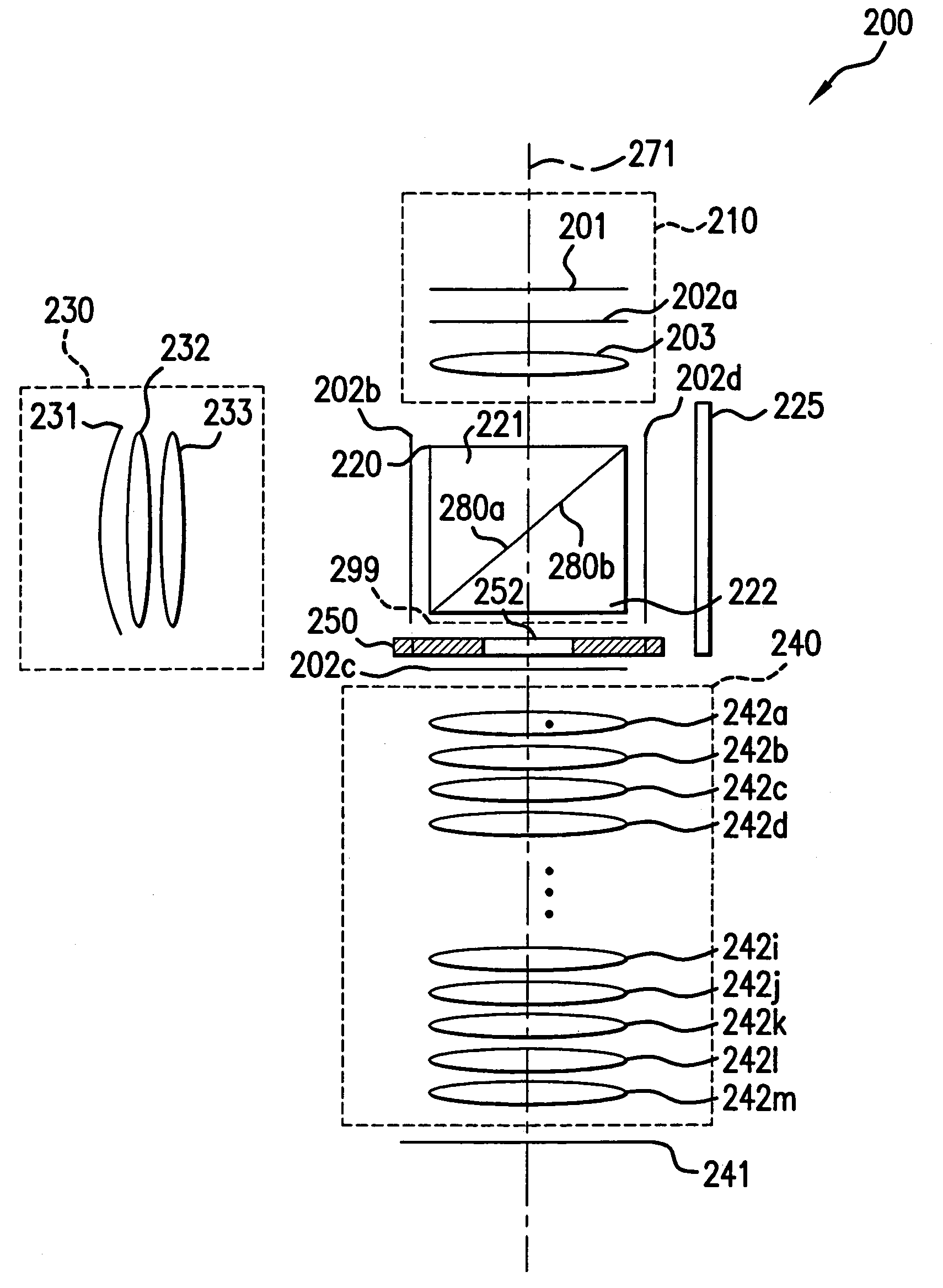
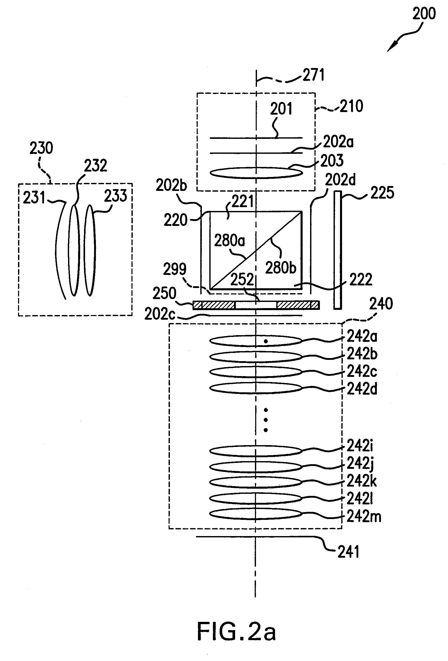
[0024]1. Overview.[0025]2. Terminology.[0026]3. Beam-Splitter Optics Design.

[0027]a. Beam Splitter Optics Design Without Spacer Plate.

[0028]b. Image Path in Beam Splitter Optics Design Without Spacer Plate.

[0029]c. Beam Splitter Optics Design With Spacer Plate.

[0030]d. Image Path in Beam Splitter Optics Design With Spacer Plate.[0031]4. Conclusion.

[0032]While the present invention is described herein with reference to illustrative embodiments for particular applications, it should be understood that the invention is not limited thereto. Those skilled in the art with access to the teachings provided herein will recognize additional modifications, applications, and embodiments within the scope thereof and additional fields in which the present invention would be of significant utility.

1. Overview

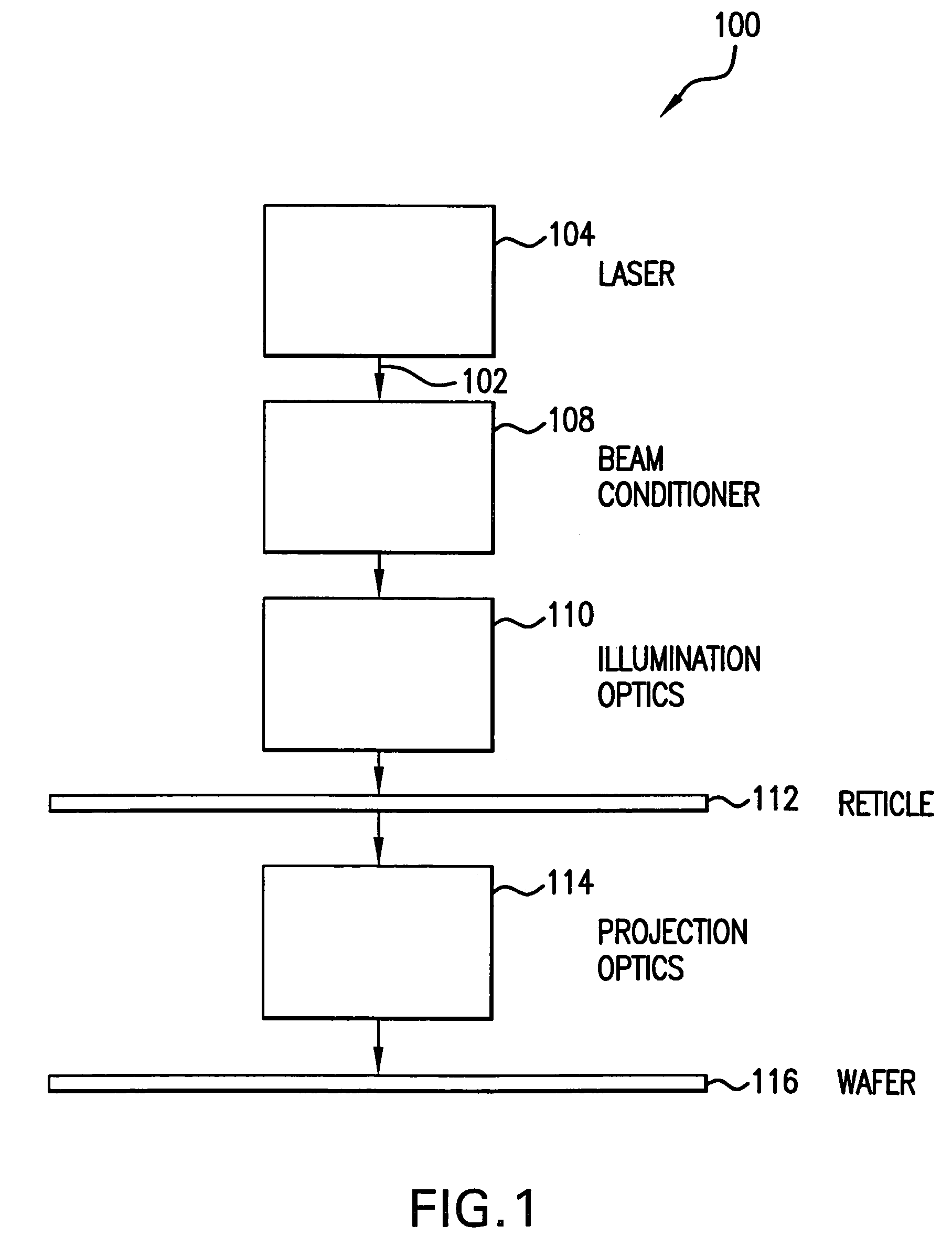
[0033]The present invention relates to lithographic systems and methods using catadioptric exposure optics that project high quality images without image flip. The present inv...


PUM


Abstract

The present invention is a catadioptric system having a reticle optical group, a beam splitter, an aspheric mirror, a baffle plate, a folding mirror and a semiconductor wafer optical group. The reticle optical group, the beam splitter and the semiconductor wafer optical group are placed on the same beam axis, different from aspheric mirror and folding mirror axis. The light passes through an image pattern on the reticle and is reflected by the beam splitter onto the aspheric mirror. The aspheric mirror reflects the light back through the beam splitter onto the folding mirror. The folding mirror reflects the light back to the beam splitter. The beam splitter reflects the light onto the semiconductor wafer optical group. A plurality of quarter wave plates can be placed in optical paths between optical elements of the present invention to change polarization of an incoming light. Before light passes through the semiconductor wafer optical group, it passes through the baffle plate, which prevents any background scattered light caused by internal reflections within the beam splitter from entering the semiconductor wafer optical group. In another embodiment, a spacer plate is inserted into the beam splitter. The spacer plate creates an offset between reticle optical group beam axis and semiconductor wafer optical group beam axis. This reduces direct passage of light from reticle optical group to semiconductor wafer optical group.

Description

CROSS REFERENCE TO RELATED APPLICATIONS[0001]This application is a continuation of U.S. Ser. No. 10 / 307,407 (now U.S. Pat. No. 6,731,374 that issued May 4, 2004), entitled “Beam-Splitter Optics Design That Maintains An Unflipped (Unmirrored) Image For A Catadioptric Lithographic System,” filed Dec. 2, 2002, which is incorporated by reference herein in its entirety.BACKGROUND OF THE INVENTION[0002]1. Field of the Invention[0003]This invention relates to an improved lithography system and method. More specifically, this invention relates to a lithography system and method using catadioptric exposure optics that projects high precision images without image flip.[0004]2. Background Art[0005]Lithography is a process used to create features on the surface of substrates. Such substrates can include those used in the manufacture of flat panel displays, circuit boards, various integrated circuits, and the like. A frequently used substrate for such applications is a semiconductor wafer. While...

Claims


Application Information

Patent Timeline
IPC IPC(8): G02B27/28G03F7/20H01L21/027
CPCG02B17/08G02B17/0892G03F7/70941G03F7/70225G03F7/70308G02B27/283H01L21/027
Inventor SEWELL, HARRY
Owner ASML HLDG NV
Why Eureka
Try Eureka