Ferroelectric memory device

a memory device and ferroelectric technology, applied in semiconductor devices, digital storage, instruments, etc., can solve the problems of large memory area and inability to increase capacitance, and achieve the effect of shortening access time and shortening access tim

Inactive Publication Date: 2005-12-06
SEIKO EPSON CORP
View PDF6 Cites 6 Cited by
  • Summary
  • Abstract
  • Description
  • Claims
  • Application Information

AI Technical Summary

Benefits of technology

[0009]With the present invention, the operation of the potential gradient correction section makes it possible to ensure that no excess voltage is applied to unselected memory cells, even during transition periods in which the selected-word-line-voltage, the unselected-word-line-voltage, the non-fixed-potential selected-bit-line-voltage, or the unselected-bit-line-voltage is switched. This makes it possible to prevent the application of an accidental over-voltage to an unselected memory cell, enabling preservation of data stored in that unselected memory cell. In addition, one of the unselected-word-line-voltage-supply-line and the unselected-bit-line-voltage-supply-line, which have a heavy connection load and slow charge / discharge speeds, is fixed to a single potential on the side at which the difference in potential gradient is not corrected. No potential gradient change occurs in the voltage supply line at the fixed potential, so no over-voltage is supplied to unselected memory cells due to a difference in potential gradient. In addition, the fixed potential makes it possible to improve the memory access speed.
[0010]The potential gradient correction section may set the magnitude of a voltage corresponding to one of the first and second differences in potential gradient which is to be reduced to be equal to or less than the magnitude of the unselection voltage. It is therefore possible to apply a voltage to each unselected memory cell that is equal to or less than the unselection voltage during a stable period in which the voltages reach to a predetermined value, even during transition periods during the switching of the voltages, making it possible to prevent deterioration of the data stored therein.
[0012]As another example, the potential gradient correction section may reduce the amount of current flowing per unit time in one of the selected-word-line-voltage-supply-line and the selected-bit-line-voltage-supply-line so as to close to the amount of current flowing per unit time in one of the unselected-word-line-voltage-supply-line and the unselected-bit-line-voltage-supply-line having an unfixed potential. In such a case, the potential gradient correction section can utilize the small current drive capability of a transistor. The potential gradient correction section could be configured by connecting a diode to that transistor.
[0013]The potential gradient correction section may increase the potential gradient of one of the unselected-word-line-voltage-supply-line and the unselected-bit-line-voltage-supply-line. In this case, the potential gradient correction section may increases the amount of current flowing per unit time in one of the unselected-word-line-voltage-supply-line and the unselected-bit-line-voltage-supply-line having an unfixed potential so as to close to the amount of current flowing per unit time, in one of the selected-word-line-voltage-supply-line and the selected-bit-line-voltage-supply-line. In such a case, in contrast to the above, the large current drive capability of a transistor can be utilized. This configuration enables a greater shortening of the access time.
[0015]The control circuit may output a signal for switching between the potential of the selected-bit-line-voltage-supply-line and the potential of one of the unselected-bit-line-voltage-supply-line and the unselected-word-line-voltage-supply-line having an unfixed voltage, substantially simultaneously with the timing at which the selected-word-line-voltage is supplied to the selected-word-line-voltage-supply-line. In such a case, the voltage selection circuit could supply the unselected-bit-line-voltage to the unselected-bit-line-voltage-supply-line substantially simultaneously with the timing at which the selected-word line-voltage is supplied to the selected-word-line-voltage-supply-line. The effect is to shorten the access time.
[0016]The control circuit may output a signal for switching between the potential of the selected-word-line-voltage-supply-line and the potential of one of the unselected-bit-line-voltage-supply-line and the unselected-word-line-voltage-supply-line having an unfixed potential, substantially simultaneously with the timing at which a selected-bit line-voltage is supplied to the selected-bit-line-voltage-supply-line. In such a case, the voltage selection circuit can supply the unselected-word line-voltage to the unselected-word-line-voltage-supply-line substantially simultaneously with the timing of the supply of the selected-bit line-voltage to the selected-bit-line-voltage-supply-line. This effect also shortens the access time.

Problems solved by technology

With this active type of ferroelectric memory device, however, the memory area is large in comparison with other known non-volatile memory devices in which memory cells are configured of single elements, such as flash memory or EEPROM, and it is not possible to increase the capacitance thereof.

Method used


Image

  • Ferroelectric memory device
  • Ferroelectric memory device
  • Ferroelectric memory device

Examples


first embodiment

[0056]A first embodiment is described below with reference to the accompanying figures.

Basic Configuration of Ferroelectric Memory Device

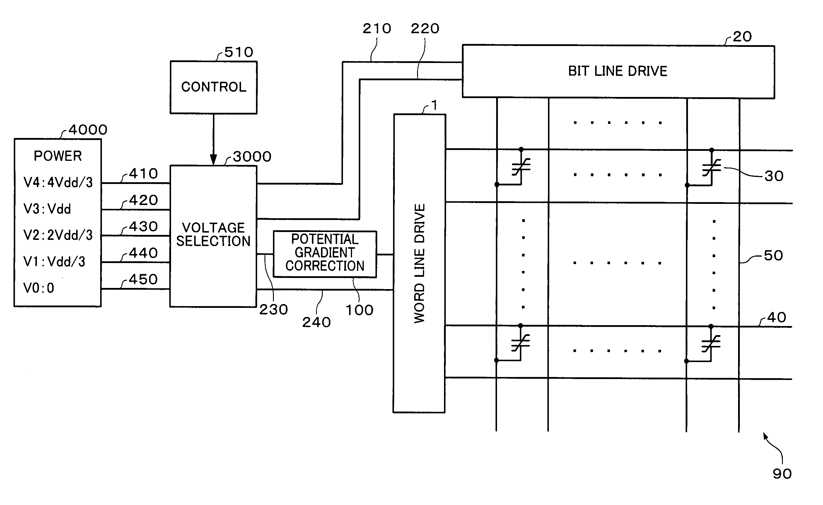
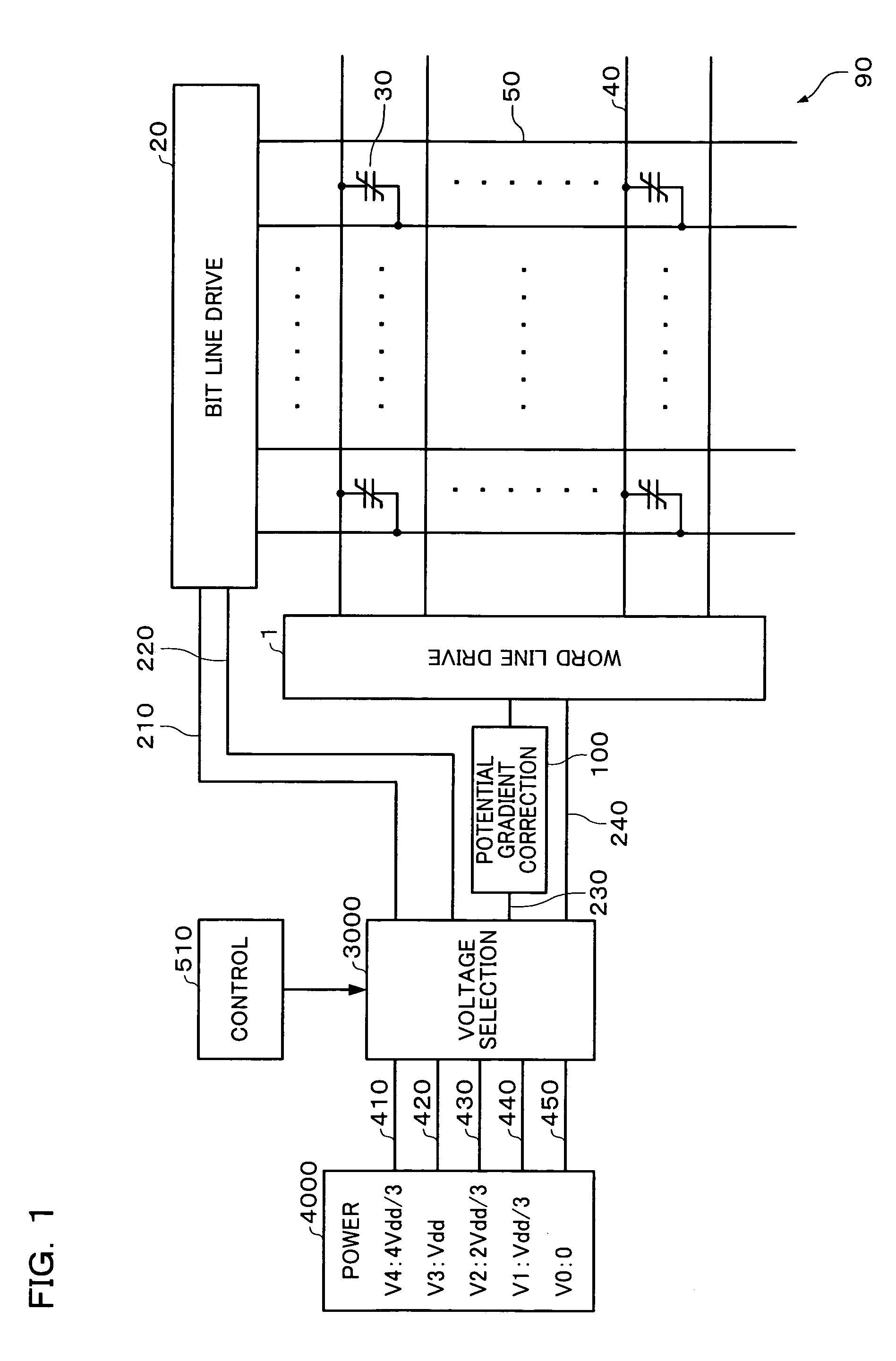
[0057]The entirety of a ferroelectric memory device in accordance with an embodiment of the present invention is shown in FIG. 1.

[0058]The ferroelectric memory device of FIG. 1 is configured of a plurality of ferroelectric capacitors (memory cells) 30 disposed at the intersections of a plurality of word lines 40 and a plurality of bit lines 50 that are arranged in a matrix. One word line 40 and one bit line 50 can be selected in order to select a specific memory cell 30 from the plurality of memory cells 30.

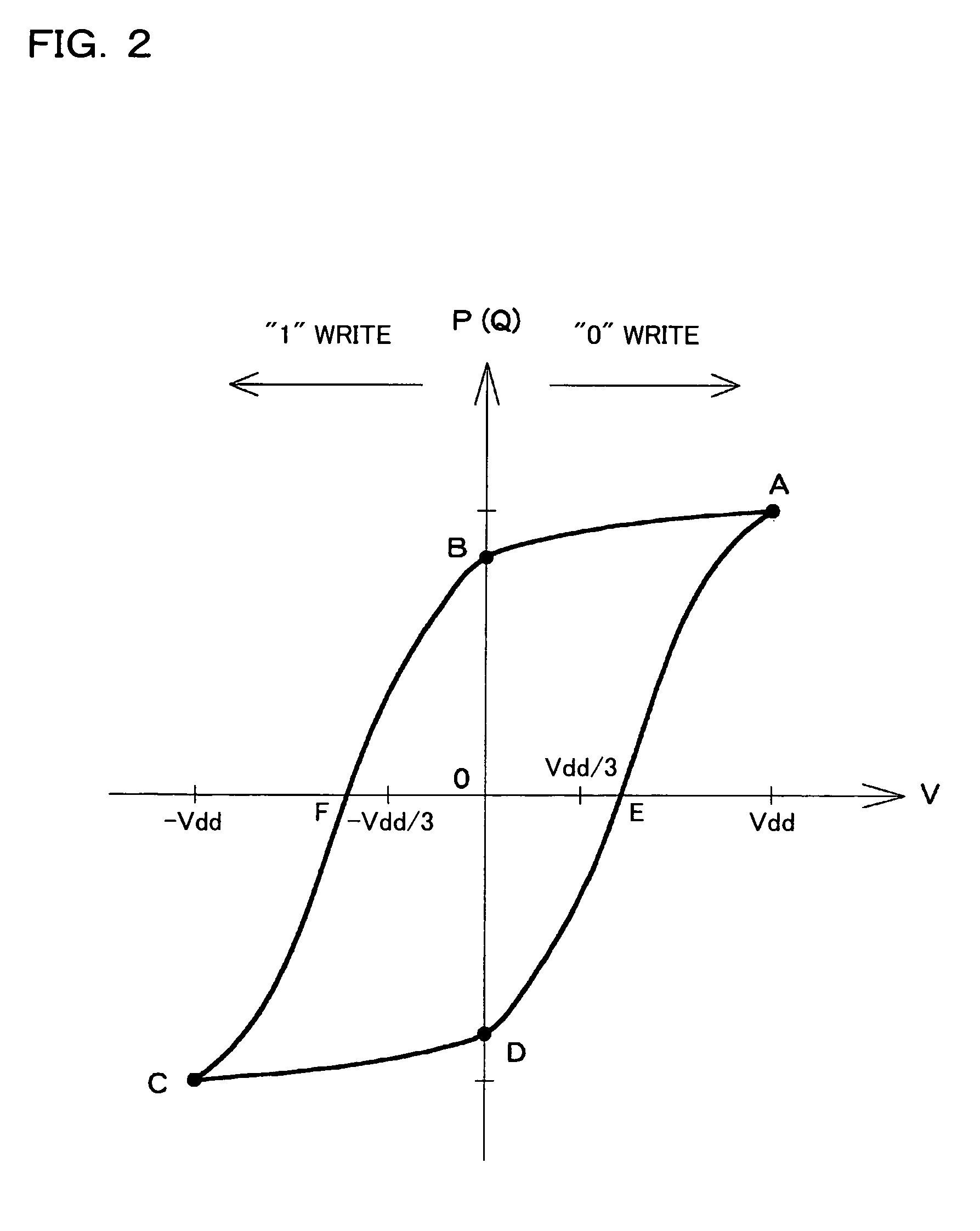
[0059]In a computer, one bit can be considered to be a quantity that enables the representation of two states, and a ferroelectric memory device is a memory device that utilizes two states expressed by the hysteresis phenomenon in the ferroelectric capacitor 30 as one bit.

[0060]In the hysteresis phenomenon, the relationship between a voltage app...

second embodiment

[0110]A second embodiment is described below, with reference to the accompanying figures.

Basic Configuration of Ferroelectric Memory Device

[0111]A block diagram of a ferroelectric memory device in accordance with this embodiment is shown in FIG. 26.

[0112]In FIG. 26, the location of the potential gradient correction section 100 differs from that of the first embodiment. In this embodiment, the potential gradient correction section 100 is provided in the selected-bit-line-voltage-supply-line 210. A voltage selection circuit 3100 is used in this embodiment instead of the voltage selection circuit 3000. The voltage selection circuit 3100 has power switching circuits 375, 385, and 395. The rest of the basic configuration is similar to that of the first embodiment.

Reading and Writing

[0113]The state of voltages applied during a read in accordance with this embodiment is shown in FIG. 27. Note that the reference numbers used in this figure are the same as those of FIG. 5. As shown in FIG. 2...


PUM


Abstract

A ferroelectric memory device enabling high-speed access has a voltage selection circuit and a potential gradient correction section. The voltage selection circuit selects a plurality of different voltages generated by a power circuit and outputs them to voltage supply lines, fixing the potential of either the unselected-word-line-voltage-supply-line or the unselected-bit-line-voltage-supply-line. The potential gradient correction section reduces one difference in potential gradient on a side with no fixed potential, which is either the difference between the potential gradient of the selected-word-line-voltage-supply-line and the potential gradient of the unselected-bit-line-voltage-supply-line, or the difference between the potential gradient of the selected bit line voltage supply line and the potential gradient unselected-word-line-voltage-supply-line.

Description

[0001]Japanese Patent Application No. 2003-7405 filed on Jan. 15, 2003 is hereby incorporated by reference in its entirety.BACKGRAOUND OF THE INVENTION[0002]The present invention relates to a ferroelectric memory device.[0003]As a ferroelectric memory device, an active ferroelectric memory including 1T / 1C cells in which one transistor and one capacitor (ferroelectric) are disposed in each cell, or including 2T / 2C cells in which a reference cell is further disposed in each cell, has been known.[0004]With this active type of ferroelectric memory device, however, the memory area is large in comparison with other known non-volatile memory devices in which memory cells are configured of single elements, such as flash memory or EEPROM, and it is not possible to increase the capacitance thereof.[0005]One non-volatile memory device that can support an increased capacitance is a ferroelectric memory device in which each memory cell acts as a ferroelectric capacitor. (Refer to Japanese Patent...

Claims


Application Information

Patent Timeline
Patent Type & Authority Patents(United States)
IPC IPC(8): G11C11/22G11C15/00H01L21/8246H01L27/10H01L27/105
CPCG11C11/22
Inventor MARUYAMA, AKIRA
Owner SEIKO EPSON CORP
Why Eureka
Try Eureka