Auto advancing radio frequency array

a radio frequency array and auto-advancing technology, applied in the field of tissue ablation systems, can solve the problems of manual procedures that are confusing, many conventional systems experience difficulty in providing an adequate amount of current to cause tissue heating and coagulation, and many physicians may experience other difficulties, so as to facilitate automatic deployment and placement, eliminate any confusion, and precise ablation of body tissue

Inactive Publication Date: 2005-12-13
BOSTON SCI SCIMED INC
View PDF19 Cites 132 Cited by
  • Summary
  • Abstract
  • Description
  • Claims
  • Application Information

AI Technical Summary

Benefits of technology

[0005]The present invention is directed to improved systems and methods that facilitate the automatic deployment and placement of a needle array for precise ablation of body tissue using RF energy. The RF ablation system of the present invention tends to eliminate any confusion as to when the needle array should be farther deployed into the tissue during step deployment ablation procedures, minimize the time to carry out such procedures, and eliminate the need for insertion track bleeding management techniques following such procedures. In one innovative aspect of the present invention, a needle array-type energy delivery system is automatically advanced or step deployed under temperature and / or impedance feedback control. In another innovative aspect of the present invention, a catheter based RF ablation system includes an auto array deployment or advancement system which may comprise a servo, an electromagnetic, an electro-pneumatic, a hydraulic, or the like, actuating mechanism, or a stepper motor. In a preferred embodiment of the present invention, a catheter based RF ablation system includes a catheter having an elongate tube and a handle connected to the tube, a needle array slidably received in the tube and handle, a servo actuated drive mechanism mounted in the handle and coupled to the needle array, and a control system coupled to the servo actuated drive and needle array. The control system preferably comprises a RF energy source, a drive controller, and a temperature and / or impedance monitoring module for step deployment at predetermined temperature and / or impedance values. The control system may also include a timer for step deployment at predetermined intervals.

Problems solved by technology

However, depending on the size of the lesion to be ablated and, thus, the size of the array used to ablate the lesion, many conventional systems experience difficulty providing an adequate amount of current to cause tissue heating and coagulation.
This manual procedure tends to be confusing because of the multiple parameters that need to be observed prior to moving on to the next deployment location.
Physicians may experience other difficulties when the lesion to be ablated is close to the dermis or is in tissue that is light in density.
However, when ablation procedures, including ablation of some liver lesions, are performed relatively close to the dermis or are performed in tissue that is especially light in density, such as the lung, the physician may have a difficult time maintaining the catheter or probe in its initial orientation.
If the physician chooses not to hold or support the probe during such procedures, the probe may sag and could push the energy delivery needles or tines into the dermis layer or other tissue areas not meant to be ablated.

Method used


Image

  • Auto advancing radio frequency array
  • Auto advancing radio frequency array
  • Auto advancing radio frequency array

Examples


Embodiment Construction

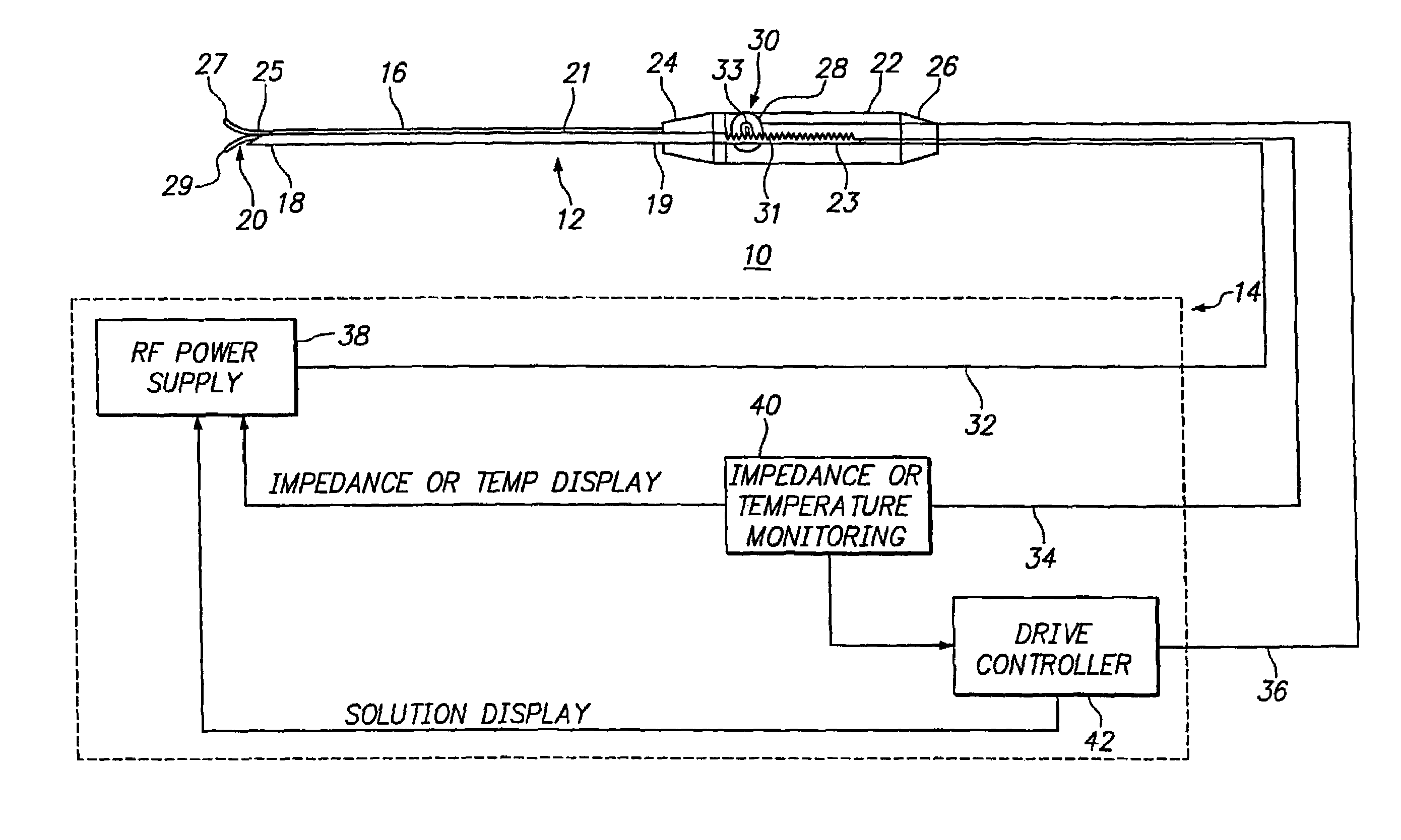
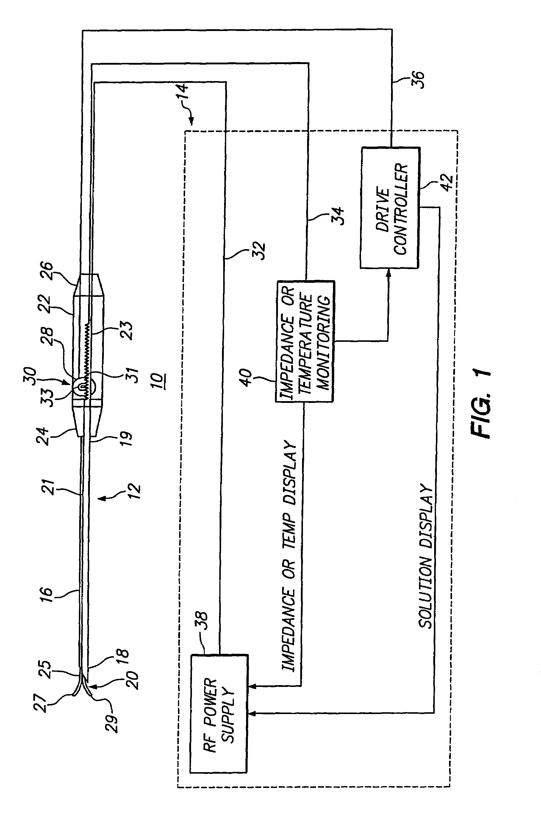
[0020]Referring in detail to the drawings, an illustrated embodiment of an improved RF ablation system of the present invention is shown. Turning to FIG. 1, the illustrated embodiment shows an overall view of a RF ablation system (10) of the present invention comprising a RF probe or catheter (12) connected to a control system (14). The RF catheter (12) preferably comprises an elongate tube (16) having distal and proximal ends (18) and (19) and a handle (22) having distal and proximal ends (24) and (26). The distal end (24) of the handle (22) is connected to the proximal end (19) of the tube (16). A passageway (not shown) extends through the tube (16) and handle (22). A needle array (20) having an elongate shaft (21) is preferably slidably received in the passageway with a proximal end (23) extending into the handle (22) and a distal end (25) extending to the distal end (18) of the tube (16) when in a retracted state and, as the illustrated embodiment shows, beyond the distal end (1...


PUM


Abstract

A system for ablating lesions in the interior regions of the human body including a RF catheter and a control system adapted to facilitate the automatic step deployment of an array-type energy delivery system positioned within the catheter. The RF catheter and control system further include an auto array deployment mechanism coupled to the array-type energy delivery system and an impedance and temperature monitoring system. In addition, the system includes a probe positioning device adapted to maintain a RF probe in a desired orientation during ablation procedures.

Description

FIELD OF THE INVENTION[0001]The present invention relates to systems and methods for ablating tissue in interior regions of the human body and, more particularly, to systems and methods that facilitate the automatic deployment and placement of a needle array for precise lesion ablation.BACKGROUND OF THE INVENTION[0002]Thermal coagulation of tissue using RF energy is frequently being used to treat maladies within the body such as liver tumor lesions. Physicians frequently make use of catheter-based RF systems to gain access to interior regions of the body. For treatment of large lesions, the catheter-based RF systems commonly employ needle array-type energy delivery devices. However, depending on the size of the lesion to be ablated and, thus, the size of the array used to ablate the lesion, many conventional systems experience difficulty providing an adequate amount of current to cause tissue heating and coagulation. To address this problem, many manufacturers simply supply a larger...

Claims


Application Information

Patent Timeline
Patent Type & Authority Patents(United States)
IPC IPC(8): A61B18/14A61B19/00A61N1/06
CPCA61B18/1482A61N1/06A61B19/26A61B2018/1467A61B2018/1475A61B90/50
Inventor GARABEDIAN, ROBERT J.RIOUX, ROBERT F.
Owner BOSTON SCI SCIMED INC
Why Eureka
Try Eureka