Function-enhanced thrombolytic AV fistula and method

a thrombolytic and functional technology, applied in the field of function-enhanced thrombolytic av fistula and method, can solve the problems of progressive narrowing of the av fistula at the junction with the vein, need to stop, etc., to reduce the associated thrombosis, enhance the function of the av fistula, and reduce the effect of thrombosis

Inactive Publication Date: 2005-12-13
LEMAITRE VASCULAR
View PDF42 Cites 98 Cited by
  • Summary
  • Abstract
  • Description
  • Claims
  • Application Information

AI Technical Summary

Benefits of technology

[0051]The present invention is directed to a thrombolytic AV fistula assembly and a method for enhancing the function of an AV fistula to help reduce any thrombosis associated therewith.
[0052]A first aspect of the invention is directed to an AV fistula function enhancing method including selecting an endoluminal prosthesis including a coiled body and a graft material covering at least part of the coiled body to create a coiled stent graft. The selecting step includes choosing an endoluminal prosthesis carrying a thrombolytic agent. The stent graft is placed within the AV fistula and optionally within at least one blood vessel to which the AV fistula is connected. The thrombolytic agent helps to reduce any thrombosis associated with the stent graft. The use of the AV fistula helps to prevent, or at least retard, the obstruction of the AV fistula by eliminating, or at least reducing, the accumulation of matter in the AV fistula. Other biologically-active agents, such as anti-restenotic agents, may also be used.
[0053]Another aspect of the invention is directed to a thrombolytic AV fistula assembly, including an AV fistula having a tubular body and a coiled stent graft housable at least partially within the AV fistula and at least one of the venous and arterial ends. The coiled stent graft includes a coiled body, a graft material at least partially covering the coiled body and a thrombolytic agent, the thrombolytic agent helping to reduce any thrombosis associated with the stent graft.
[0054]The turns of the stent graft at the vein / AV fistula junction may be spaced apart from one another so to insubstantially or partly hinder fluid flow along the vein. The turns of the stent graft may also be such as to effectively block fluid flow along the vein.

Problems solved by technology

One problem associated with AV fistulas is the progressive narrowing of the AV fistula at the junction with the vein.
Such obstructions occur when vascular muscle cells begin growing inwardly causing, for example, thrombosis within the AV fistula.
However, there still exists the need to stop, or at least slow, the obstruction of the AV fistula to prolong the patency of the graft.

Method used


Image

  • Function-enhanced thrombolytic AV fistula and method
  • Function-enhanced thrombolytic AV fistula and method
  • Function-enhanced thrombolytic AV fistula and method

Examples


Embodiment Construction

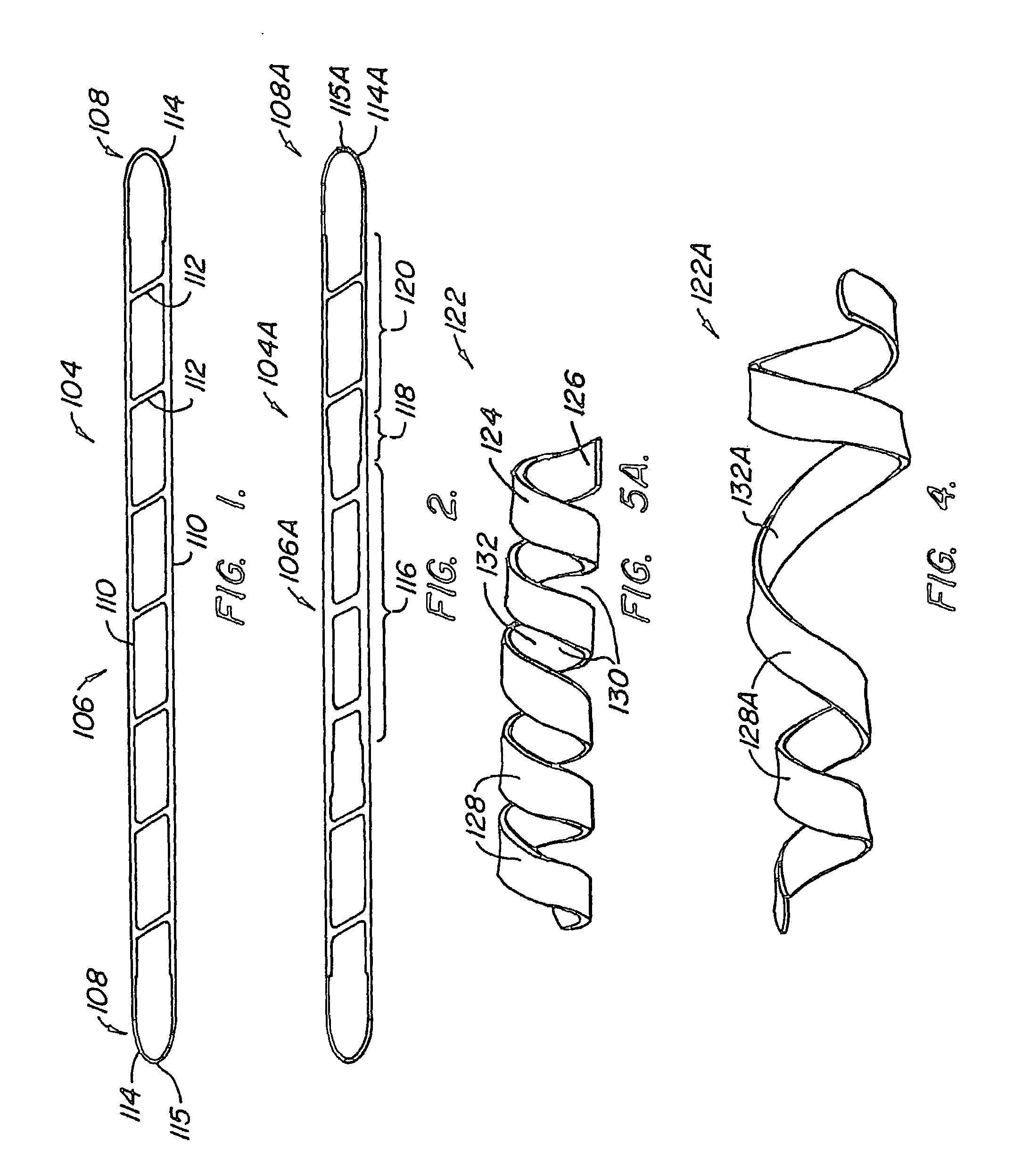
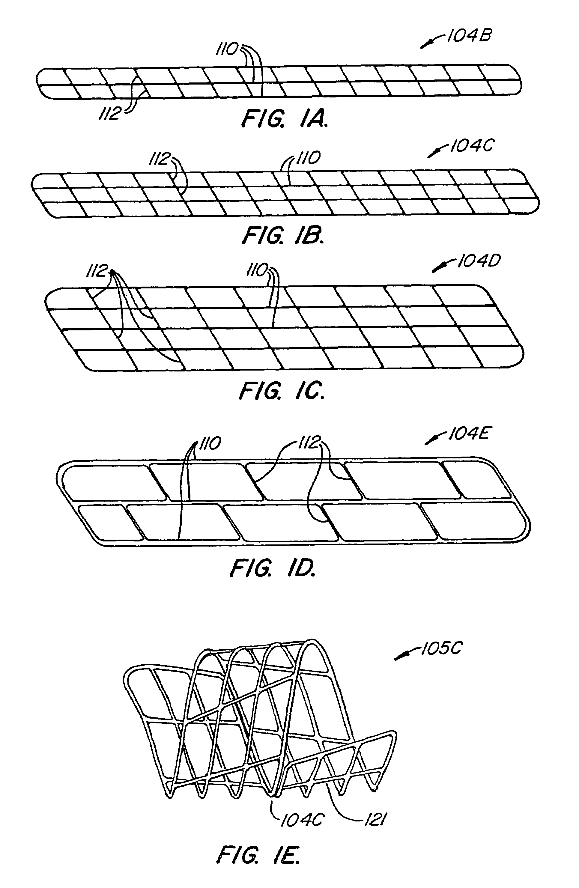
[0088]FIG. 1 illustrates a stent blank 104 used to create a coiled stent similar to that shown in FIGS. 3, 4 and 5A. Stent blank 104 includes a main body portion 106 and first and second end portions 108. Main body portion 106 includes side edge or rail elements 110 connected by connector or rung elements 112 to define openings 113 therethrough. Rung elements 112 are, as shown in FIG. 1, at an angle to rail elements 110 so that when stent blank 104 is formed into a coiled stent and tightly wrapped about an introducer catheter, such as in FIG. 7A, rung elements 112 are axially-extending so that they lie flat for a tighter wrap.

[0089]End portions 108 are thinner and thus more flexible than main body portion 106. In addition, end portions 108 have an inwardly tapering portion 114 terminating at a blunt tip 115. The shape of end portions 108 and the lessened stiffness of the end portions, compared to body portion 106, help to prevent tissue trauma during use. This type of coiled stent i...


PUM

PropertyMeasurementUnit
lengthaaaaaaaaaa
diameteraaaaaaaaaa
diameteraaaaaaaaaa

Abstract

A coiled stent graft, including a thrombolytic agent, is positionable within an AV fistula and optionally into one or both of the artery and the vein (6) to help reduce or eliminate blockages within the blood vessel at the junction between the AV fistula and the blood vessel.

Description

CROSS-REFERENCE TO OTHER APPLICATIONS[0001]This is a continuation in part of U.S. patent application Ser. No. 09 / 608,734 filled Jun. 30, 2000 now U.S. Pat. No. 6,585,760, and U.S. patent application Ser. No. 09 / 910,703 filed Jul. 20, 2001, which is a continuation in part of U.S. patent application Ser. No. 09 / 740,597 filled Dec. 19, 2000. U.S. patent application Ser. No. 09 / 910,703 incorporates by reference the following U.S. Pat. No. 6,248,122 B1 issued Jun. 19, 2001; U.S. Pat. No. 6,238,430 B1 issued May 29, 2001; U.S. patent application Ser. No. 09 / 400,955 filed Sep. 22, 1999; and U.S. patent application Ser. No. 09 / 608,281 filed Jun. 30, 2000.BACKGROUND OF THE INVENTION[0002]A fistula is an abnormal passage typically between two organs, such as an artery and a vein. An arterio-venous (AV) fistula is a natural or an artificial graft, typically made of ePTFE (expanded PTFE), between a vein and an artery. An AV fistula, as used herein, also includes naturally-occurring native tissu...

Claims


Application Information

Patent Timeline
Patent Type & Authority Patents(United States)
IPC IPC(8): A61F2/00A61F2/06A61F2/88A61L31/02A61L31/04A61L31/16
CPCA61F2/88A61L31/022A61L31/048A61L31/16C08L27/18A61F2250/0067A61L2300/416A61L2300/42A61L2300/604A61L2300/622A61F2210/0076
Inventor BARCLAY, BRUCE JFOGARTY, THOMAS J.
Owner LEMAITRE VASCULAR
Why Eureka
Try Eureka