Constant current driving circuit

a constant current driving and circuit technology, applied in the direction of electric variable regulation, process and machine control, instruments, etc., can solve the problems of high power consumption of high-precision circuits, slow response speed of high-precision circuits, and inability to respond quickly, so as to reduce power consumption, suppress unnecessary circuit power consumption, and respond quickly

Inactive Publication Date: 2005-12-13
FUJITSU LTD
View PDF9 Cites 10 Cited by
  • Summary
  • Abstract
  • Description
  • Claims
  • Application Information

AI Technical Summary

Benefits of technology

[0013]It is accordingly an object of the present invention to provide a constant current circuit that has a circuit configuration that reduces power consumption while maintaining a quick response characteristic, and suppresses unnecessary circuit power consumption, and to provide an optical communication system that suppresses increase in power supply power and thus requires a minimum heat radiation structure by using the constant current circuit.

Problems solved by technology

However, the conventional constant current driving circuits have the following problems.
While the circuit configurations are simple, the circuit configurations have a problem in that the load current varies depending on individual variations and changes in the environment such as temperature and the like.
Since the control transistor controls the load current by consuming power, the high-precision circuit has a problem of high power consumption by the circuit.
However, the high-precision and low-power-consumption circuit has a slow response speed and is thus unable to respond quickly.
Hence power consumption of a combination of the circuit and the load is Power supply voltage×Supply current.
Thus there is a circuit power consumption depending on the power supply voltage in addition to power consumption by the load.
This circuit power consumption is unnecessary power consumption.
However, since the pulse waveform is smoothed by the diode and the coil, the high-precision and low-power-consumption circuit is not capable of quick response in at least a pulse period or more.

Method used


Image

  • Constant current driving circuit
  • Constant current driving circuit
  • Constant current driving circuit

Examples


first embodiment

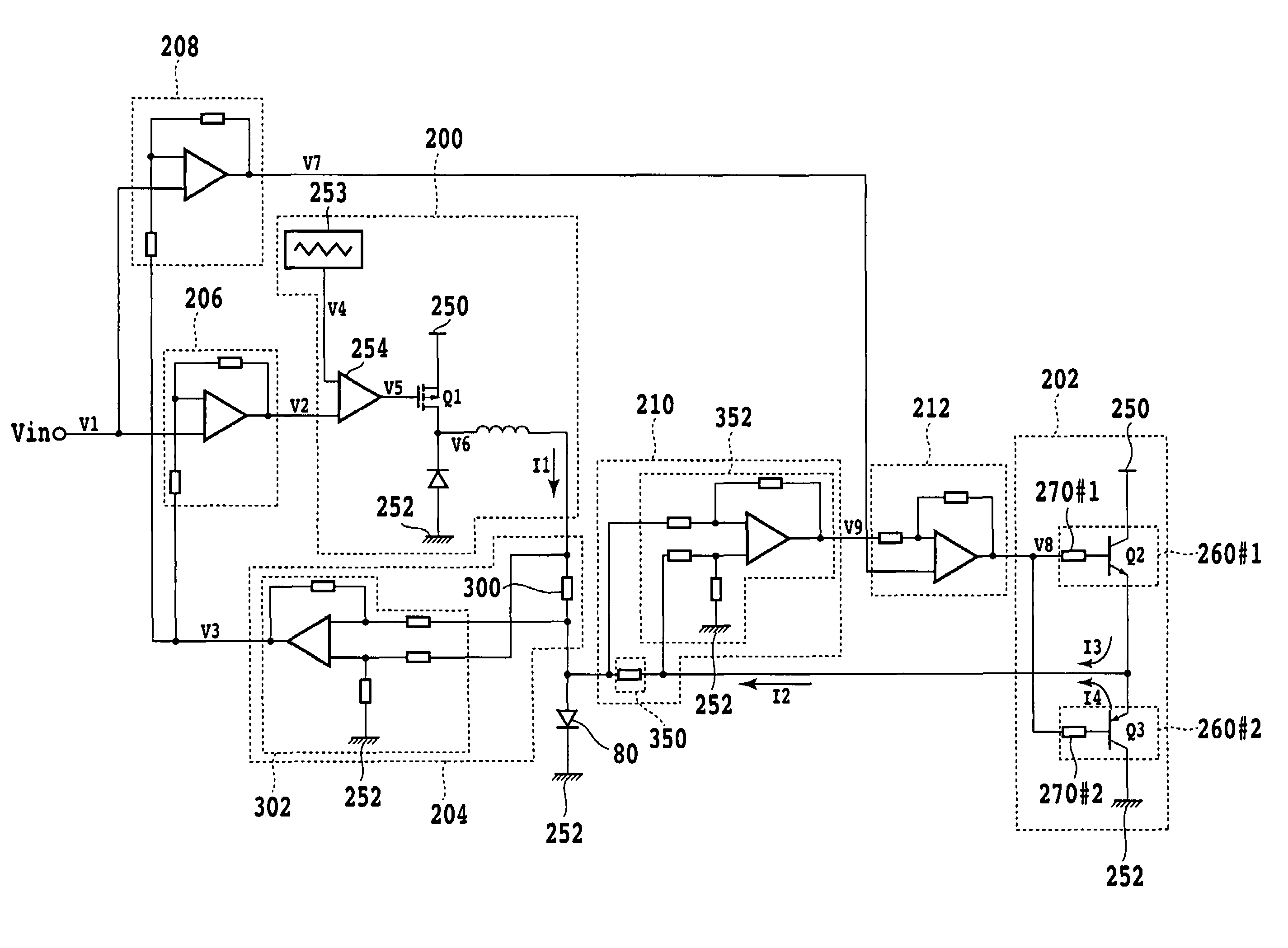
[0038]FIG. 3 is a diagram of a configuration of a constant current driving circuit according to a first embodiment of the present invention. As shown in FIG. 3, the constant current driving circuit includes a first driver circuit 200, a second driver circuit 202, a first current detecting circuit 204, a first difference detecting circuit 206, a second difference detecting circuit 208, a second current detecting circuit 210, and a third difference detecting circuit 212.

[0039]The first driver circuit 200 is a low-consumption constant current driving circuit. The first driver circuit 200 has a triangular wave generator 253, a comparator 254, a PFET (switch) Q1, a choke coil L, and a diode D. The triangular wave generator 253 is a circuit for generating a triangular wave V4 having a predetermined cycle in a certain voltage range (for example 0V to +5 V). The comparator 254 compares the voltage level of the triangular wave V4 input to a plus terminal of the comparator 254 with the voltag...

second embodiment

[0052]FIG. 5 is a diagram of a configuration of a constant current driving circuit according to a second embodiment of the present invention. In FIG. 5, substantially the same components as components in FIG. 3 are identified by the same reference numerals. In the second embodiment, a second current detecting circuit 500 outputs a second current detection signal V8 obtained by converting a combined current of driving currents I1 and 12 into voltage to a second difference detecting circuit 502. The second difference detecting circuit 502 outputs a difference voltage V7 between an input voltage V1 and the second current detection signal V8 to a second driver circuit 202. The second current detecting circuit 500 for example includes a monitoring resistance 510 and an operational amplifier 512. The resistance 510 is a monitoring resistance that converts the combined current of the driving current I1 and the driving current I2 into a voltage. The operational amplifier 512 calculates a po...

third embodiment

[0055]FIG. 7 is a diagram of a configuration of a constant current driving circuit according to a third embodiment of the present invention. In FIG. 7, substantially the same components as components in FIG. 3 are identified by the same reference numerals. In the third embodiment, a first current detecting circuit 600 is formed by a monitoring resistance 650 having one terminal connected to a ground 252 and another terminal connected to a negative terminal of a load 80. The first current detecting circuit 600 outputs a first current detection signal obtained by converting a combined current of driving currents I1 and 12 into voltage. A first difference detecting circuit 602 outputs a first difference detection signal to make zero a difference between an input voltage Vi and the first current detection signal. A second difference detecting circuit 604 calculates a difference between the input voltage Vi and the first current detection signal to output a second difference detection si...


PUM


Abstract

A constant current driving circuit for supplying a constant current to a load circuit includes: a first driver circuit having a pulse width converting circuit for converting a first difference detection signal into a pulse signal having a pulse width corresponding to a signal level of the first difference detection signal, a switch turned on / off on a basis of the pulse signal, and a smoothing circuit for supplying a smoothed first load current to the load circuit; a first current detecting circuit for converting the first load current into a first voltage corresponding to the first load current, and outputting a first current detection signal; a second driver circuit for supplying a second load current to the load circuit on a basis of a signal level of a second difference detection signal; a second current detecting circuit for converting the second load current into a second voltage corresponding to the second load current, and outputting a second current detection signal; a first difference detecting circuit for calculating the first difference detection signal to make zero a difference between the first current detection signal and an input voltage; a second difference detecting circuit for detecting a difference voltage between the first current detection signal and the input voltage, and outputting a third difference detection signal; and a third difference detecting circuit for detecting a difference voltage between the third difference detection signal and the second current detection signal, and outputting the second difference detection signal.

Description

CROSS REFERENCE TO RELATED APPLICATIONS[0001]This is a continuing application, filed under 35 U.S.C. §111 (a), of International Application PCT / JP2003 / 002658, filed Mar. 6, 2003.BACKGROUND OF THE INVENTION[0002]1. Field of the Invention[0003]The present invention relates to a constant current driving circuit used in an optical communication device, an optical system, and the like.[0004]2. Description of the Related Art[0005]An example of circuit configuration using device characteristics, an example of a high-precision circuit, an example of high-precision and low-power-consumption configuration, and the like are generally used for constant current driving circuits.(1) Example of Circuit Configuration Using Device Characteristics[0006]FIG. 13A and FIG. 13B are diagrams showing a conventional example of circuit configuration of a constant current driving circuit using device characteristics. FIG. 13A shows an example of configuration using a FET. FIG. 13B shows an example of configur...

Claims


Application Information

Patent Timeline
Patent Type & Authority Patents(United States)
IPC IPC(8): G05F1/56
CPCG05F1/56
Inventor TAMURA, YUJIOTSUKA, TOMOYUKI
Owner FUJITSU LTD
Why Eureka
Try Eureka