
Method and apparatus for fault simulation of semiconductor integrated circuit

a technology of integrated circuits and fault simulation methods, applied in the field of fault simulation, can solve the problems of inability to simulate fault models using this fault simulation method, no list of detectable faults, and limited fault models that can be simulated, so as to facilitate a better understanding and improve the efficiency of testing

Inactive Publication Date: 2005-12-13
ADVANTEST CORP
View PDF18 Cites 65 Cited by
  • Summary
  • Abstract
  • Description
  • Claims
  • Application Information

AI Technical Summary

Benefits of technology

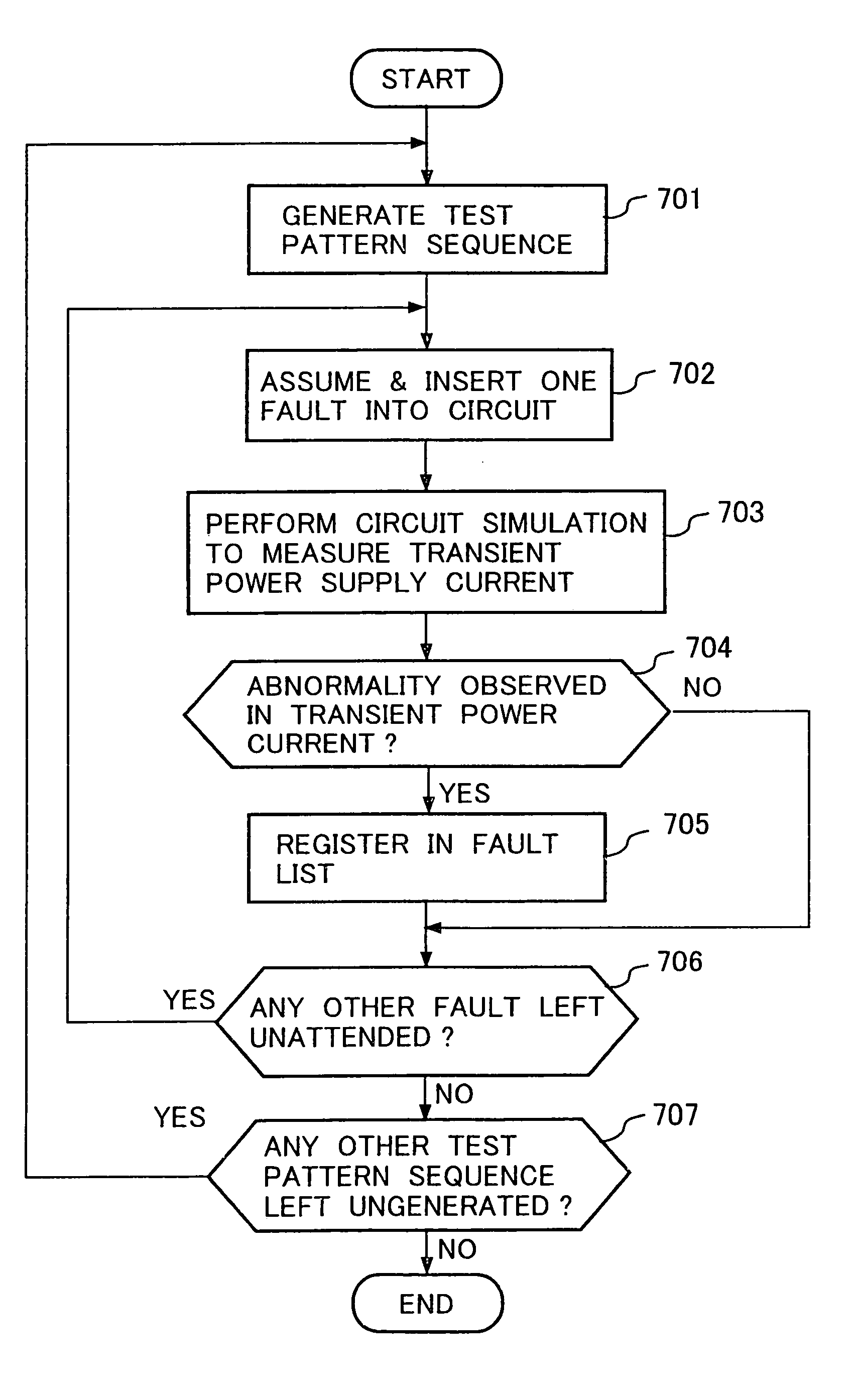
[0009]With this method, it is possible to make a list of faults detectable by the transient power supply current testing using a certain test pattern sequence for conventionally undetectable delay faults or open faults leading to the delay faults—this significantly improves the efficiency of testing for such delay and open faults.
[0014]With the fault simulator of the above construction, it is possible to make a list of faults detectable by the transient power supply current testing using a certain test pattern sequence for conventionally undetectable delay faults or open faults leading to the delay faults—this significantly improves the efficiency of testing for such delay and open faults.
[0016]With this method, it is possible to make a list of faults detectable by the transient power supply current testing using a certain test pattern sequence for delay, open and parameter abnormality faults which have been impossible to detect. Hence, this method significantly improves the efficiency of testing for such delay and open faults.
[0018]With this fault simulator, it is possible to make a list of faults detectable by the transient power supply current testing using a certain test pattern sequence for delay, open and parameter abnormality faults which have been impossible to detect. Hence, this fault simulator significantly improves the efficiency of testing for such delay and open faults.Principle of the Invention
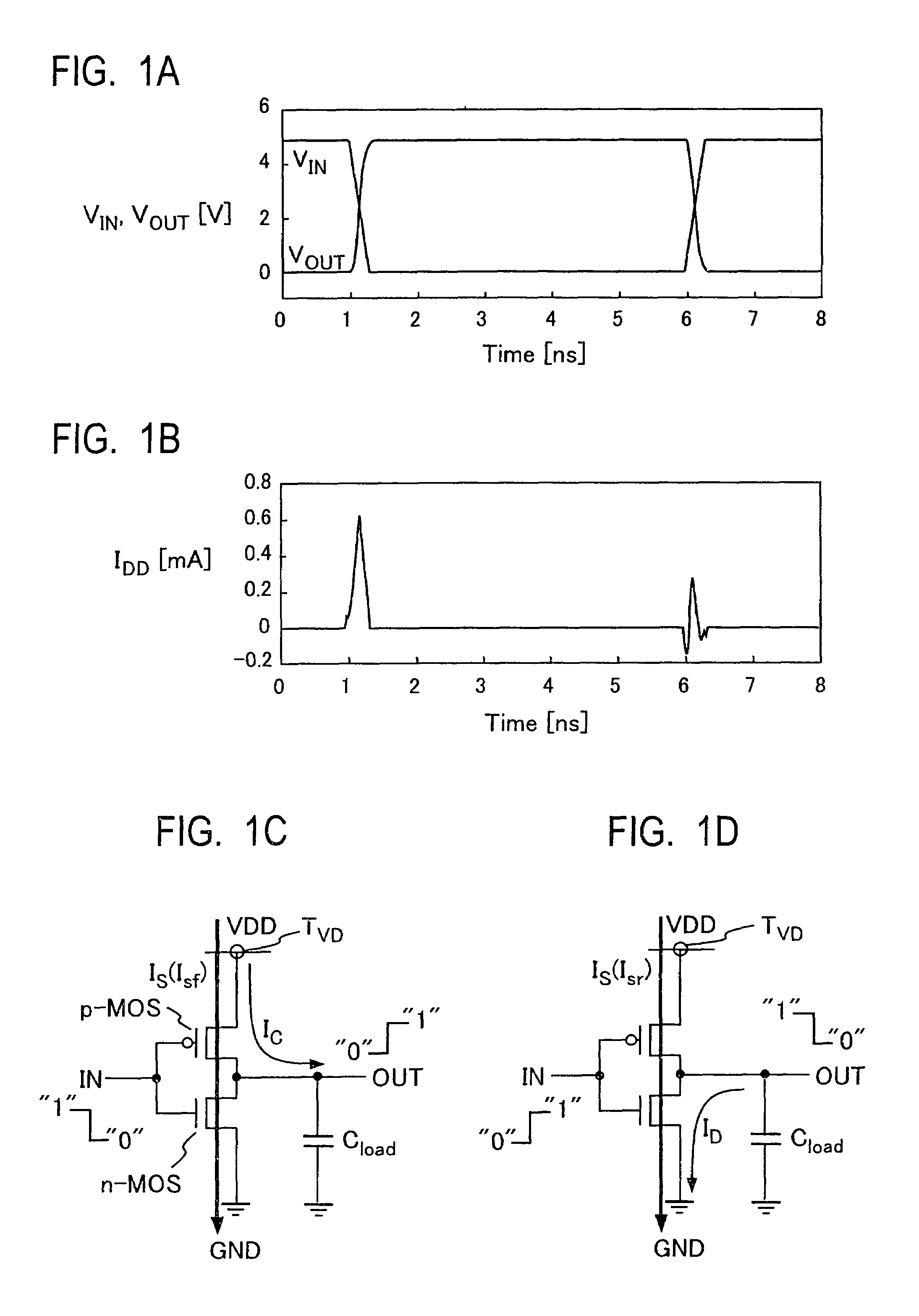
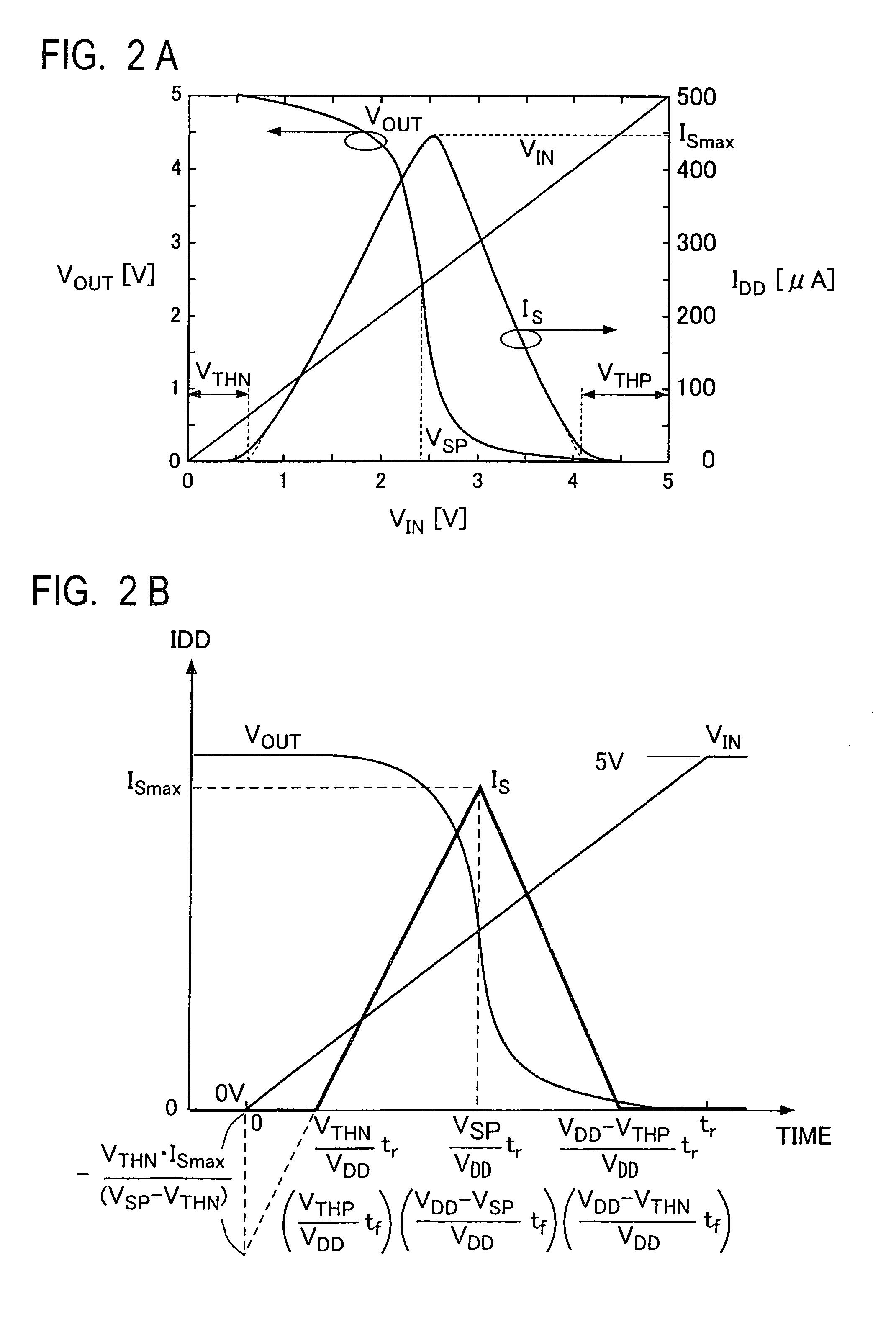
[0060]The transient power supply current is a transient current flowing across the power supply terminal of the IC, and its observability higher than a voltage signal is ensured. Hence, the delay fault detecting scheme using the transient power supply current assures higher observability for the delay fault than does a delay fault detecting scheme using the voltage signal. For example, the delay fault detecting scheme using a voltage signal, for instance, cannot detect the delay fault unless the voltage signal propagates to the output signal line of an IC. In contrast thereto, the delay fault detecting scheme using the transient power supply current signal can detect the delay fault since it is possible to measure a transient power supply current signal of a pulse width corresponding to the delay time of the path over which the voltage signal has propagated even if the voltage signal does not propagate to the output signal line of the IC. Accordingly, the delay fault detecting scheme using the transient power supply current does not require the propagation of the voltage signal to the output signal line of the IC, and hence it is less limited by the test pattern generation than the conventional delay fault detecting scheme using the voltage signal. Accordingly, test patterns can be generated with more ease. In the extreme, for example, even if test pattern sequences are randomly generated and applied to the circuit under test, the delay fault detecting scheme using the transient power supply current permits detection of a delay fault in the path that is activated by the test pattern sequences applied thereto.Fault List Making Method (Fault Simulation)

Problems solved by technology

According to the fault simulation method using the logic simulation, however, the fault model that can be simulated is limited only to a single stuck-at-fault (Stuck-At-0 or Stuck-At-1) which is a fault that one signal line is stuck at a certain state (“0”or “1”).
Therefore, it is impossible with this fault simulation method to simulate, with high sensitivity, a multiple stuck-at-fault that plural signal lines are stuck at “0” or “1”, a delay fault, a short fault between lines, and so on; hence, no lists of detectable faults can be made.
Hence, this method is incapable of making lists of detectable faults on transient phenomena of semiconductor ICs such as delay fault and open faults affecting the delay time and abnormalities of local or global process parameters (a sheet resistance, an oxide film thickness, and so forth).

Method used


Image

  • Method and apparatus for fault simulation of semiconductor integrated circuit
  • Method and apparatus for fault simulation of semiconductor integrated circuit
  • Method and apparatus for fault simulation of semiconductor integrated circuit

Examples


Embodiment Construction

[0110]Now, a description will be given of embodiments of the present invention.

[0111]FIG. 18 illustrates in block form an example of the construction of a fault simulator for use in an embodiment of the present invention. The fault simulator, denoted generally by 100, comprises: test pattern generating means 101 which generates test patterns one after another for input to a semiconductor IC under test; a logic simulator 102 which performs logic simulations of the operation of the IC under test by sequentially applying thereto the test patterns from the test pattern generating means 101, then calculates logic signal value sequences occurring in signal lines of the IC under test, and stores them in a memory 102M in correspondence with the respective test pattern sequences; and a fault list generating means 103 which generates list of faults detectable by a transient power supply current testing for each test pattern sequence through the use of the logic signal value sequence for each ...


PUM


Abstract

A test pattern sequence is generated (101), then a logic simulation of the operation of an IC under test in the case of applying each test pattern of the test pattern sequence, and a logic signal value sequence occurring in each signal line of the IC under test (102). The logic signal value sequence in each signal line is used to register in a fault list parts (a logic gate, signal line or signal propagation path) in which a fault (a delay fault or an open fault) detectable by a transient power supply current testing using the test pattern sequence is likely to occur (103).

Description

BACKGROUND OF THE INVENTION[0001]The present invention relates to a fault simulation method and apparatus which make a list of faults in a semiconductor integrated circuit that are detectable using a certain test pattern sequence.[0002]In a conventional fault simulation of a semiconductor integrated circuit (hereinafter referred to as a semiconductor IC or simply as an IC), predetermined test patterns are input to the semiconductor IC with faults assumed to lie therein, then response output values available from its output terminal are calculated by a logic simulation to detect variations in the output values relative to those obtainable under fault-free conditions, and the results thus obtained are summarized as a comparative table of assumed faults and input / output logic values, which table is commonly called a fault dictionary. This is a conventional way of making a list of faults detectable by the test patterns. In the testing of an IC each test pattern is input thereto, and its...

Claims


Application Information

Patent Timeline
IPC IPC(8): G01R31/30G01R31/3183G01R31/28G06F11/22G06F17/50
CPCG01R31/318342G01R31/3004
Inventor ISHIDA, MASAHIROYAMAGUCHI, TAKAHIROHASHIMOTO, YOSHIHIRO
Owner ADVANTEST CORP
Learn More