MEMS microcapillary pumped loop for chip-level temperature control

a micro-capillary pump and micro-cpl technology, applied in the field of micro-electromechanical systems, can solve the problems of significant limiting factors and increase in complexity of electronic packages, and achieve the effect of improving the performance of micro-cpl

Inactive Publication Date: 2005-12-20
AIR FORCE UNITED STATES OF AMERICA THE AS REPRESENTED BY THE SEC OF +1
View PDF16 Cites 42 Cited by
  • Summary
  • Abstract
  • Description
  • Claims
  • Application Information

AI Technical Summary

Benefits of technology

[0009]A micropump can be used to enhance the performance of the micro-CPL in accordance with the invention, or the micro-CPL can function p...

Problems solved by technology

However, as electronic packages increase in complexity and continue to ...

Method used


Image

  • MEMS microcapillary pumped loop for chip-level temperature control
  • MEMS microcapillary pumped loop for chip-level temperature control
  • MEMS microcapillary pumped loop for chip-level temperature control

Examples


Embodiment Construction

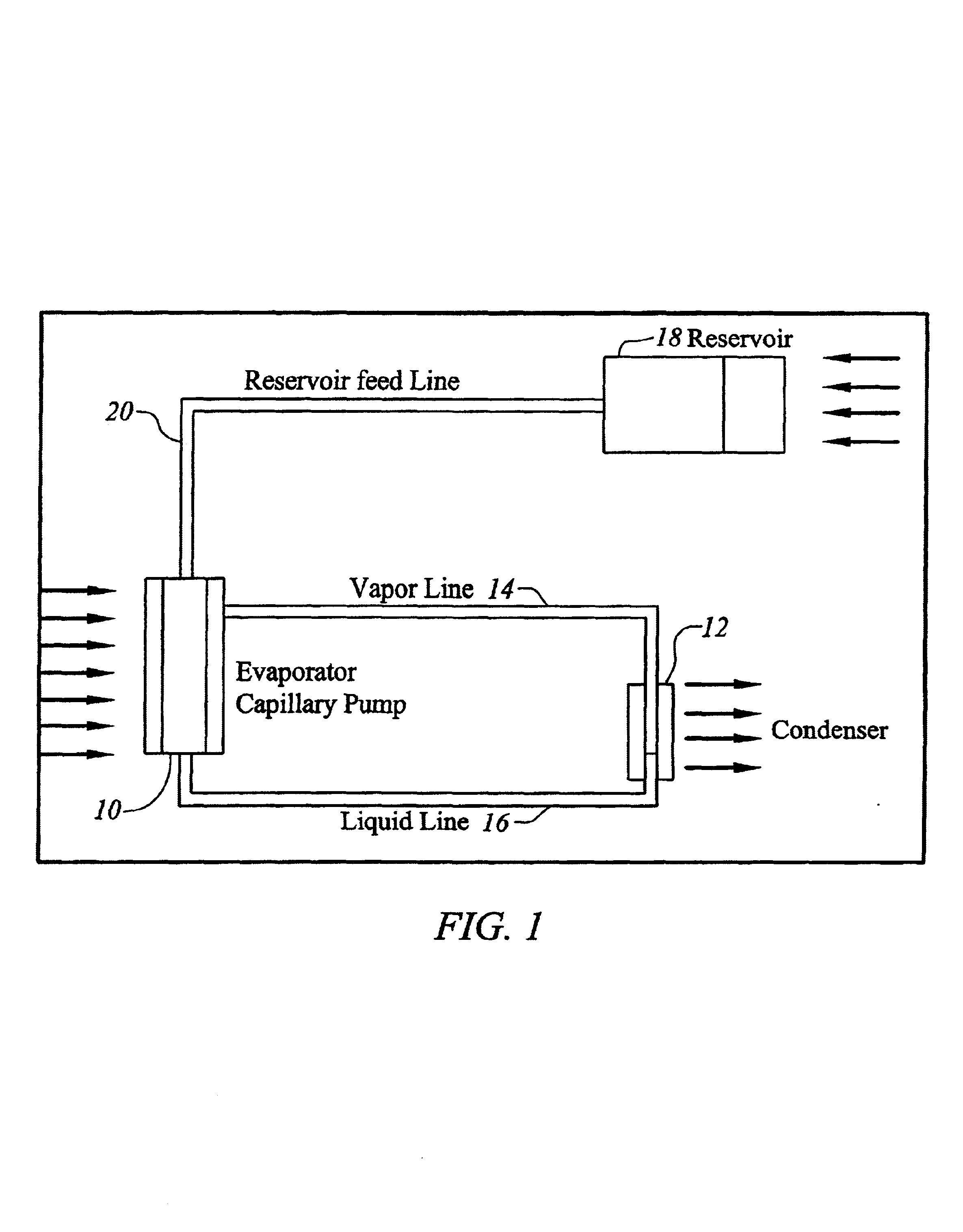
[0017]FIG. 1 is a schematic of a microcapillary pumped loop including a micro-CPL. The structure includes an evaporator 10, a condenser 12 with a vapor line 14 connecting vapor from evaporator 10 to condenser 12, and a liquid line 16 for coupling condensed fluid in condenser 12 back to evaporator 10. A fluid reservoir 18 is connected by a reservoir feed line 20 to evaporator 10 in initially charging the loop with fluid and replenishing fluid. Reservoir 18 includes a hole (not shown) for receiving coolant from a pressurized source outside of the loop. Additionally, condenser 12 can include a hole to an outside pump when the loop is employed with a pump in an active system.

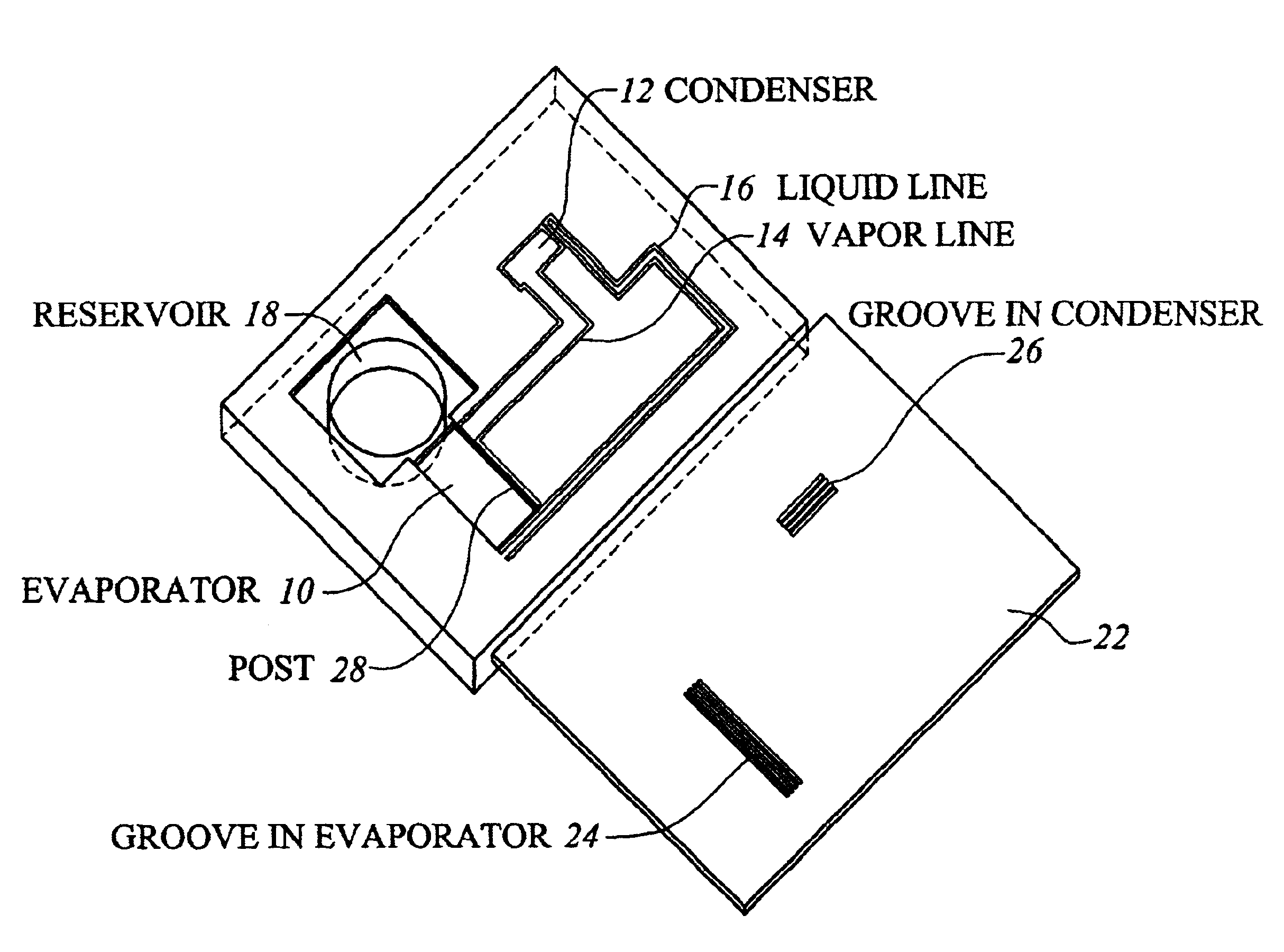
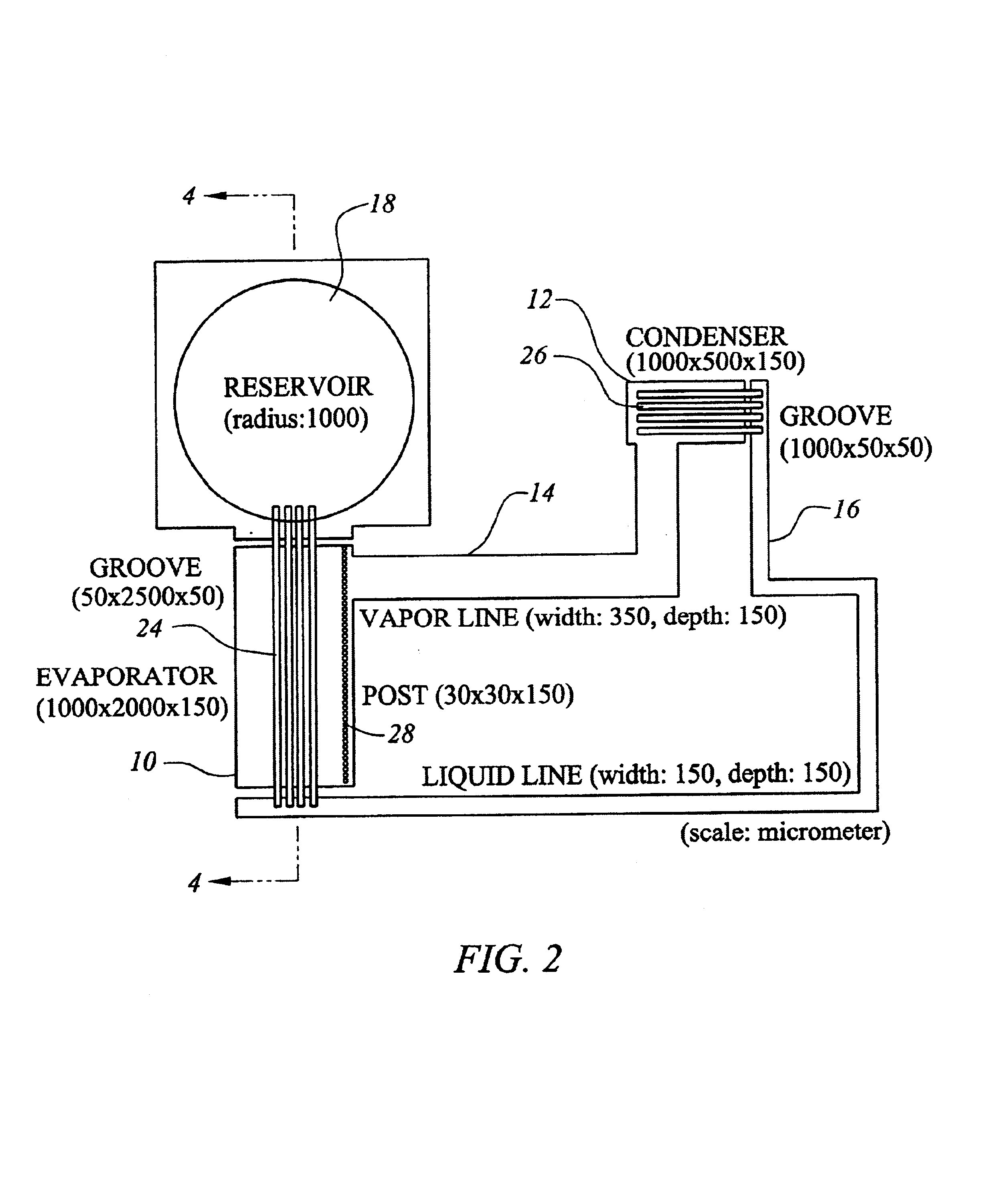
[0018]FIG. 2 is a plan view of a micro-CPL in accordance with one embodiment of the invention which is fabricated in two mating substrates as will be described with reference to FIG. 3. Again, evaporator 10 is coupled to condenser 12 by means of a vapor line 14, and condensed liquid from condenser 12 is coupled to l...


PUM


Abstract

A microcapillary pumped loop (CPL) for chip level temperature control includes two mating substrates which define an evaporator, a condenser, and a reservoir for a liquid. A first substrate includes a vapor line which couples vapor from the evaporator to the condenser, and a liquid line which couples liquid from the condenser back to the evaporator. A wicking structure for the evaporator is formed by etching in the second substrate. The wicking structure couples the evaporator to the reservoir and to the liquid line. The condenser includes a plurality of grooves formed in the second substrate which couples liquid from the condenser to the liquid line.

Description

CROSS-REFERENCES TO RELATED APPLICATIONS[0001]This application claims priority from Provisional Application No. 60 / 306,264 filed Jul. 17, 2001 which is incorporated herein for all purposes.STATEMENT AS TO RIGHTS TO INVENTIONS MADE UNDER FEDERALLY SPONSORED RESEARCH OR DEVELOPMENT[0002]Government Funding[0003]This invention was made with Government support under contract number F33615-97-1-2788 awarded by the United States Air Force. The Government has certain rights in this invention.BACKGROUND OF THE INVENTION[0004]This invention relates generally to the cooling of micro-devices such as integrated circuits for example, and more particularly the invention relates to a microelectromechanical system (MEMS) which provides a microcapillary pumped loop (CPL) for heat removal from micro-devices.[0005]Heat sinks have long been used with electronic components such as power transistors and integrated circuits for the removal of heat generated by the component. However, as electronic packages...

Claims


Application Information

Patent Timeline
IPC IPC(8): F28D15/04H01L23/427
CPCB82Y30/00F28D15/043H01L23/427H01L2924/0002H01L2924/00
Inventor KIRSHBERG, JEFFREYYERKES, KIRK L.LIEPMANN, DORIAN
Owner AIR FORCE UNITED STATES OF AMERICA THE AS REPRESENTED BY THE SEC OF
Why Eureka
Try Eureka