Optical recording medium and method for making the same

a technology of optical recording media and optical recording layer, which is applied in the field of optical recording media, can solve the problem that the supporting substrate cannot be used in the standard process, and achieve the effect of reducing the average surface roughness (ra) of the ink-receiving layer and simplifying the production process

Inactive Publication Date: 2005-12-20
TDK CORPARATION
View PDF9 Cites 9 Cited by
  • Summary
  • Abstract
  • Description
  • Claims
  • Application Information

AI Technical Summary

Benefits of technology

[0023]As is described above, in the present invention, the bonding layer that bonds the light-transmissive substrate to the supporting substrate is composed of a material containing an epoxy resin instead of radically polymerizable UV-curable resin generally employed. Thus, the light-transmissive substrate can be tightly fixed onto the supporting substrate without UV irradiation through the supporting substrate.
[0024]Furthermore, the supporting substrate is white or in a bright color close to white. Thus, no colored layer, such as one containing white ink, is necessary between the ink-receiving layer and the supporting substrate, thereby simplifying the production process. The average surface roughness (Ra) of the ink-receiving layer can be notably minimized. Thus, color development and luster comparable to images shot by film cameras can be obtained by using inkjet printers.

Problems solved by technology

However, whereas a supporting substrate is usually bonded to a light-transmissive substrate by UV irradiation after superimposing the light-transmissive substrate on the supporting substrate with a radically polymerizable UV-curable resin therebetween, such a standard-process cannot be employed if the supporting substrate is colored.

Method used


Image

  • Optical recording medium and method for making the same
  • Optical recording medium and method for making the same
  • Optical recording medium and method for making the same

Examples


Embodiment Construction

[0036]The preferred embodiments of the present invention will now be described in detail with reference to the attached drawings.

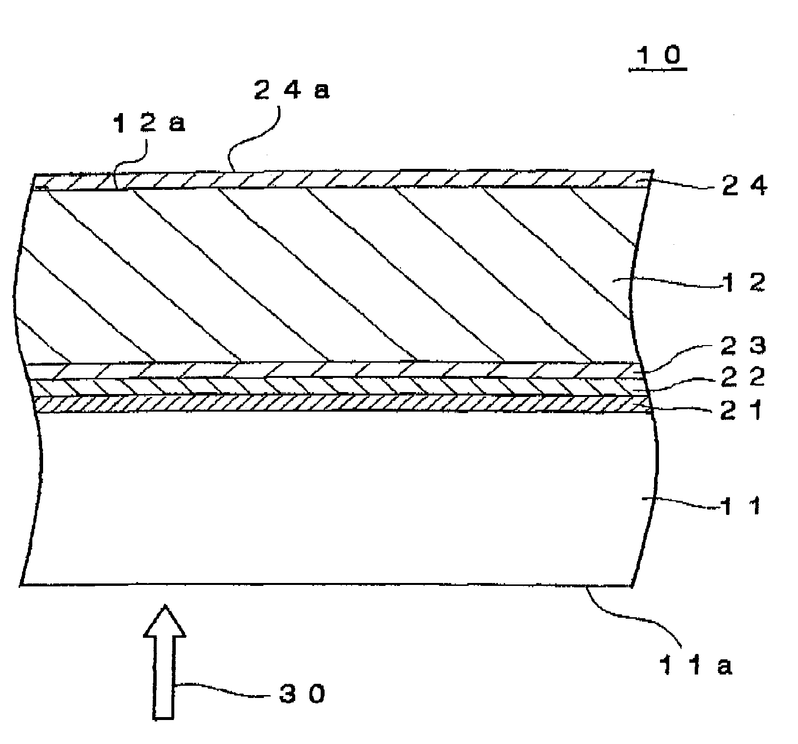
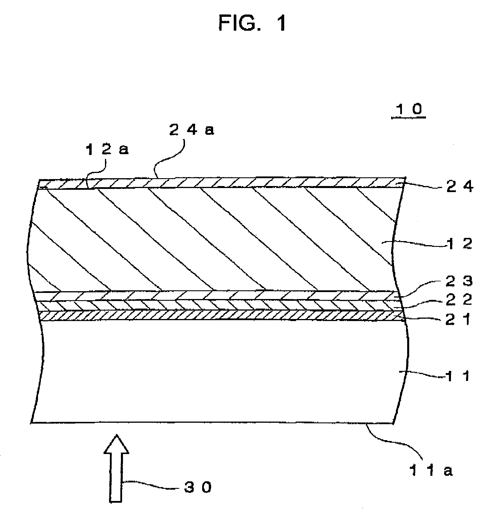
[0037]FIG. 1 is a schematic cross-sectional view showing the structure of an optical recording medium according to a preferred embodiment of the present invention.

[0038]An optical recording medium 10 of this embodiment is disk-shaped and has a diameter of about 120 mm and a thickness of about 1.2 mm. As show in FIG. 1, the optical recording medium 10 includes a light-transmissive substrate 11, a supporting substrate 12; a functional layer 21, a protective layer 22, and a bonding layer 23 between the light-transmissive substrate 11 and the supporting substrate 12; and an ink-receiving layer 24 disposed on the surface of the supporting substrate 12. The supporting substrate 12 is sometimes referred to as a “dummy substrate”.

[0039]Data can be read and / or written by irradiating a light-incident surface 11a with a laser beam 30 while rotating the optical record...


PUM

PropertyMeasurementUnit
Raaaaaaaaaaa
surface roughnessaaaaaaaaaa
thicknessaaaaaaaaaa

Abstract

An optical recording medium is made by a step of bonding a light-transmissive substrate to a supporting substrate having a brightness of 8 or more and a saturation of 4 or less via a bonding layer composed of an epoxy resin; and a step of forming a transparent ink-receiving layer on a surface of the supporting substrate remote from the light-transmissive substrate. The bonding using the epoxy resin is conducted by a method of curing the resin by using a cationic initiator, a method of curing the resin by an addition reaction between the resin and a crosslinking agent containing an active hydrogen compound, a method of curing the resin by heating, or the like. In this invention, the bonding layer is composed of a material containing an epoxy resin instead of a radically polymerizable UV-curable resin typically used. Thus, although UV irradiation through the supporting substrate is not possible, the light-transmissive substrate can be securely bonded to the supporting substrate.

Description

TECHNICAL FIELD[0001]The present invention relates to optical recording media and methods for making the optical recording media. In particular, it relates to an optical recording medium having a label surface, onto which objects can be printed, at the back of a light-incident surface.BACKGROUND ART[0002]Recently, optical recording media, such as compact discs (CDs) and digital versatile discs (DVDs), are widely used to record large-volume digital data. In particular, optical recording media that allow users to record data thereto (recordable media) are rapidly gaining popularity, and many people now use the recordable media to easily and cost-effectively record large-volume digital data, such as image data and music data. Accompanying the popularity of such optical recording media, there is a growing demand for recording media that allow the users to print objects onto the surfaces opposite to the light-incident surfaces (hereinafter, simply referred to as the “label surface”) usin...

Claims


Application Information

Patent Timeline
Patent Type & Authority Patents(United States)
IPC IPC(8): B32B3/02B32B27/00G11B7/24G11B7/26G11B23/40
CPCB32B27/00B41M5/502G11B7/252G11B7/256G11B7/26G11B23/40G11B7/24018B41M2205/34B41M2205/36B41M2205/42Y10T428/21
Inventor SATOU, JUNICHIUSAMI, MAMORUSAKAI, YOSHIMIITOGA, AKIRA
Owner TDK CORPARATION
Why Eureka
Try Eureka