Battery charging and/or DC power supply circuitry

Inactive Publication Date: 2005-12-20
MOBILETRON ELECTRONICS
View PDF2 Cites 167 Cited by
  • Summary
  • Abstract
  • Description
  • Claims
  • Application Information

AI Technical Summary

Benefits of technology

[0007]The primary objective of the present invention is to provide an improved battery charging and/or DC power supply circuitry, which avoids not only the huge size and the heavyweight

Problems solved by technology

A conventional battery charger normally employs a high-cost, huge, and heavy transformer for stepping down the alternate current (AC) line voltage to get charging current for charging the battery.
However, such battery charger is too heavy to be conveniently portable due to the heavy transformer.
However, since the silicon controlled rectifier (SCR) fails to be turned off by the gate terminal once triggered, while encountering the condition of unstable AC power, like power phase deviation is occurred in the power supply of the power plant, o

Method used


Image

  • Battery charging and/or DC power supply circuitry
  • Battery charging and/or DC power supply circuitry
  • Battery charging and/or DC power supply circuitry

Examples


Embodiment Construction

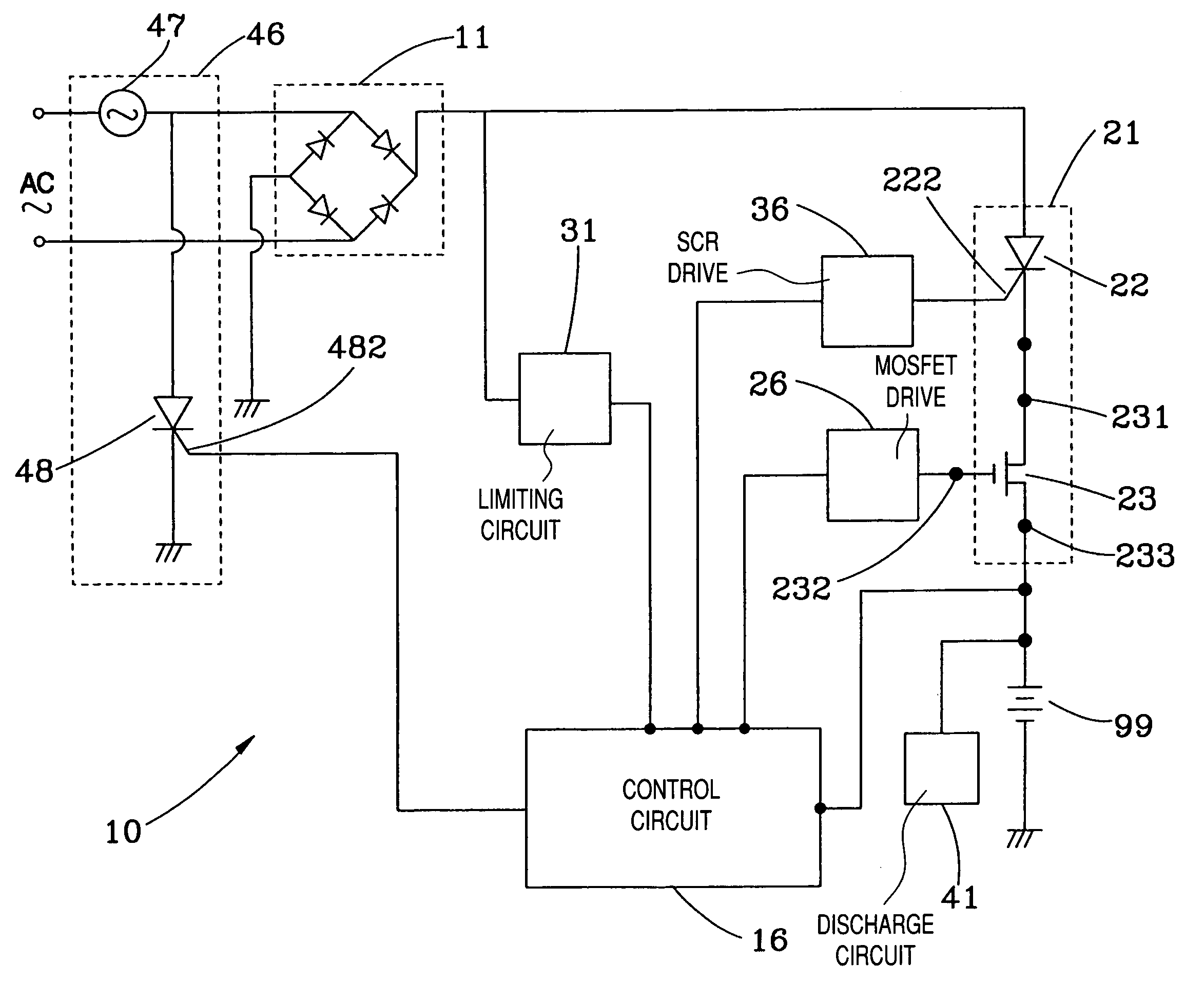
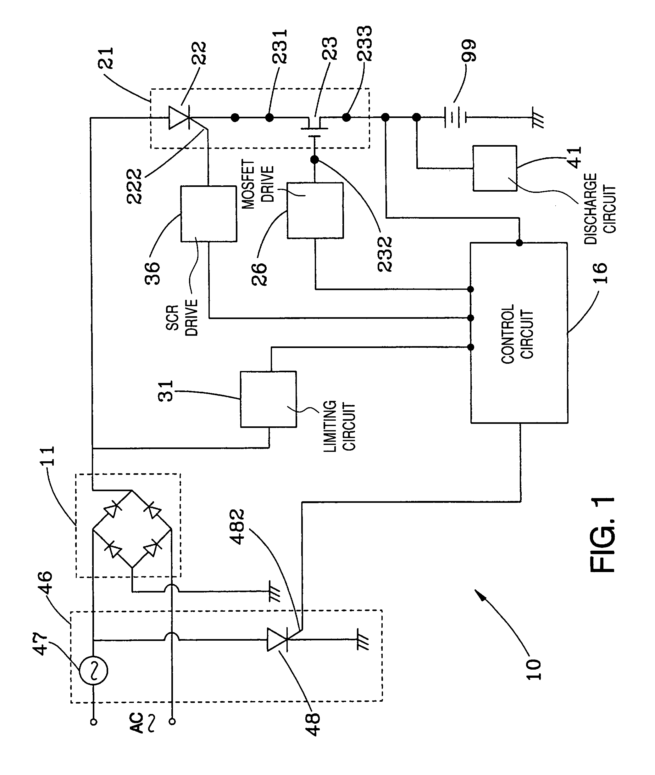
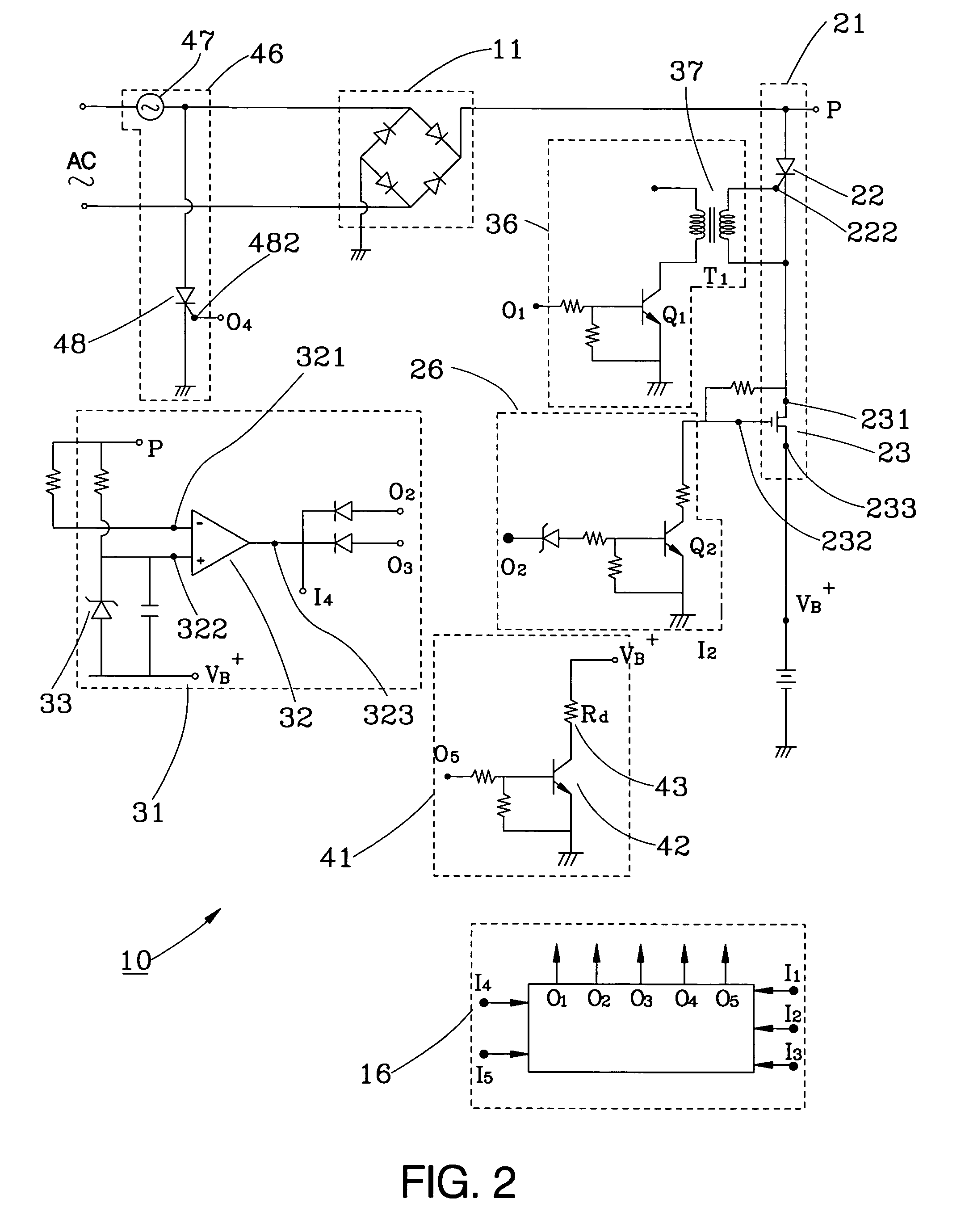
[0017]Referring to FIGS. 1–2, a battery charging and / or DC power supply circuitry 10 constructed according to a first preferred embodiment of the present invention is comprised of a rectifier unit 11, a control circuit 16, a semiconductor switch unit 21, an MOS switch drive circuit 26, a level-limiting circuit 31, an SCR drive circuit 36, a discharging circuit 41, and a protection circuit 46.

[0018]The rectifier unit 11 is a bridging rectifier in this embodiment and electrically connected with an AC power source (not shown) for rectifying a positive full wave of the AC power source (not shown) to a plurality of positive half waves.

[0019]The control circuit 16 includes a microprocessor, which is a programmable single chip, for predetermined calculation and control.

[0020]The semiconductor switch unit 21 includes a first SCR 22 serially connected with an input terminal 231 of an MOS switch 23, which is a P channel metal-oxide-semiconductor field-effect transistor (MOSFET) or a bipolar p...


PUM


Abstract

A battery charging and/or DC power supply circuitry employs a control circuit through an SCR drive circuit and an MOS drive circuit to control when to turn on/off a semiconductor switch unit and to turn on the semiconductor switch unit while an initial section of each positive half wave of an AC power source and an terminating section of the same are located below a predetermined level for intercepting partial power for charging. While charging a battery, the circuitry is lightweight, small-sized, and to enhance the life of the battery. While being a DC power supply, the circuitry is small-sized, high-efficiency, and low-cost.

Description

BACKGROUND OF THE INVENTION[0001]1. Field of the Invention[0002]The present invention relates generally to electronic devices, and more particularly to a battery charging and / or DC power supply circuitry.[0003]2. Description of the Related Art[0004]A conventional battery charger normally employs a high-cost, huge, and heavy transformer for stepping down the alternate current (AC) line voltage to get charging current for charging the battery. However, such battery charger is too heavy to be conveniently portable due to the heavy transformer.[0005]A transformerless pulse battery charging circuitry was developed to eliminate the drawback of the aforementioned conventional battery charger. As shown in FIG. 7, a conventional pulse battery charging circuitry primarily employs a control circuit to intercept the low voltage from a negative-slope side of the AC power and the employs the low voltage as a charging power source to charge the battery. However, since the silicon controlled rectif...

Claims


Application Information

Patent Timeline
IPC IPC(8): H02J7/02H02J7/04H02M7/217
CPCH02J7/022H02J7/04H02M7/2176H02J7/02H02J2207/20H02J7/007
Inventor WEI, CHEN-KU
Owner MOBILETRON ELECTRONICS
Why Eureka
Try Eureka