Vehicle mounted travel surface and weather condition monitoring system

a technology of weather condition monitoring and vehicle mounting, which is applied in the direction of instruments, ways, instruments, etc., can solve the problems of no real-time weather sensing apparatus available for vehicle mounting, no instrumentation commercially installed on motor vehicles, and limited mobile systems available. to achieve the effect of reducing the development of future adverse conditions

Inactive Publication Date: 2005-12-20
WEATHER INSIGHTS
View PDF85 Cites 55 Cited by
  • Summary
  • Abstract
  • Description
  • Claims
  • Application Information

AI Technical Summary

Benefits of technology

[0013]It is a still further object of the present invention to provide a reliable display of information to the vehicle operator of actual and pending conditions of the road surface. It is a still further object of the invention to provide an apparatus for sensing actual road conditions that can function automatically or manually and which permits automatic or manual control of distribution of on board conditioning materials.
[0014]It is a still further object of the present invention to provide a system for remote sensing and evaluation of material present on a roadway surface which includes a means for extracting sufficient information to determine the characteristics of the composition of the surface material and utilizing user input information as well as local weather conditions at the vehicle location, as well as at fixed locations, to calculate the amount of additional material, if any, and what type, to be applied to the road surface to mitigate the development of future adverse conditions. This may involve utilization of look up tables, of historical data for the location, continual updating of such tables with actual data from the location, and utilization of algorithms for predicting future conditions at the site.

Problems solved by technology

However, such instrumentation has commercially not been installed on motor vehicles.
Currently there is no real time weather sensing apparatus available that can be vehicle mounted which determines weather conditions such as wind speed and direction, temperature, humidity, precipitation events, water content and rates of deposition, and barometric pressure.
However, available mobile systems are limited to basic moisture detection and temperature monitoring systems.
These systems are simplistic and do not tell the operator the critical information needed under all conditions, such as, what is the composition of and at what temperature will the particular material actually on the road surface freeze?
Such a system is unavailable today.

Method used


Image

  • Vehicle mounted travel surface and weather condition monitoring system
  • Vehicle mounted travel surface and weather condition monitoring system
  • Vehicle mounted travel surface and weather condition monitoring system

Examples


first embodiment

[0042

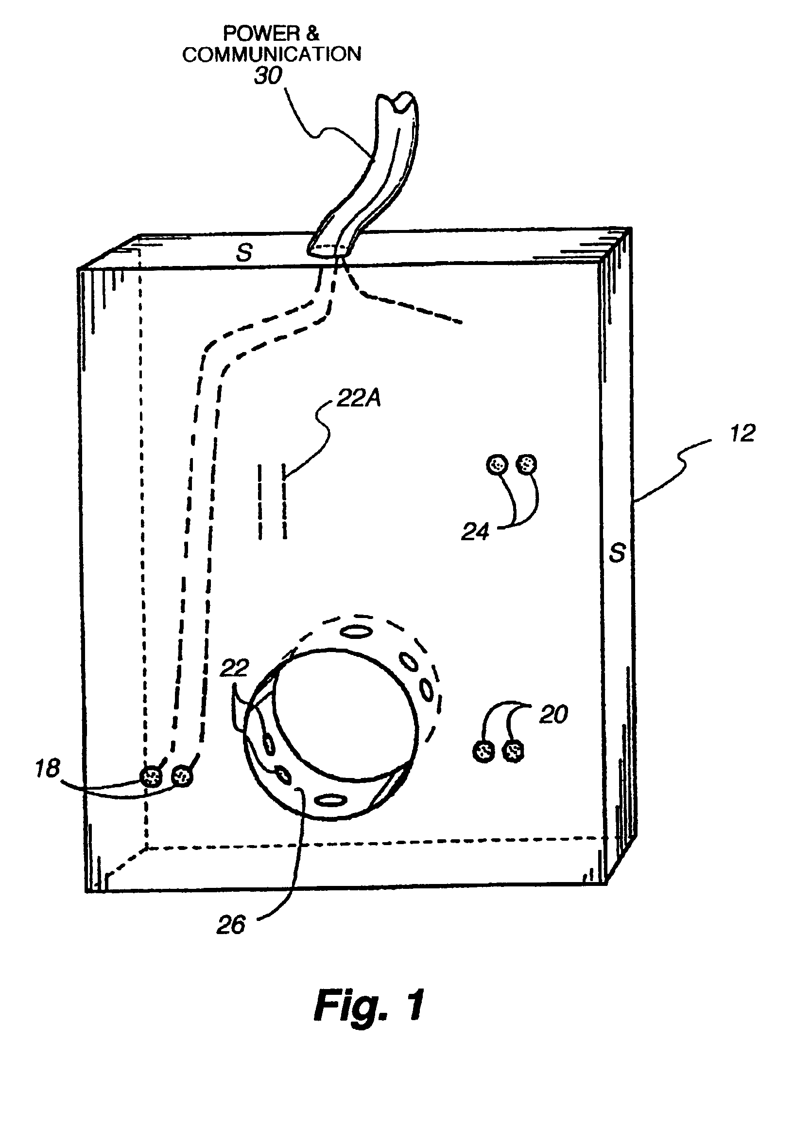
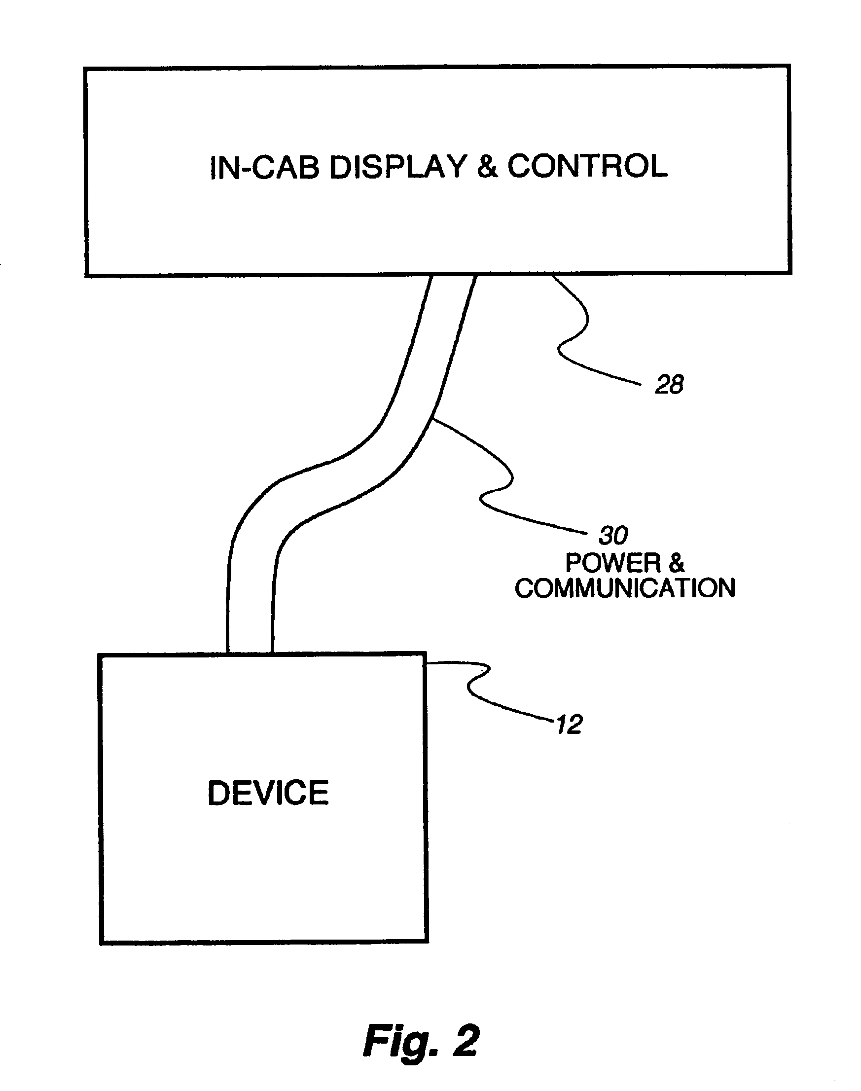
[0043]Referring now to FIGS. 1 through 3, a first embodiment of the apparatus of the invention includes a platform 12 which is typically vertically mounted behind a vehicle wheel 14 for the surface material monitoring portion if the present invention. in this application, the platform 12 replaces and also operates as a conventional mud flap on the vehicle 10. A similar platform for the atmospheric monitoring portion of the present invention may be mounted in various positions as shown on the upper portions of the vehicle 10 in FIG. 3.

[0044]As stated above, one of the objects of this portion of the invention is to provide a unique multipurpose mounting platform 12, such as is shown in FIG. 1, that enables the temporary use of materials 16 or periodic examination of materials which are typically discharged from a vehicle wheel / road surface interface to measure certain characteristics of the materials that have left a roadway surface (surface materials), and to also determine cert...

second embodiment

[0066

[0067]A second embodiment of the surface condition sensing system in accordance with the invention is shown in FIGS. 4-8. The system in accordance with the second embodiment is specifically directed to determining the freezing temperature of a surface material. It includes an apparatus 38 that collects material from the road surface into a chamber, freezes it, determines the freezing temperature, communicates the data appropriately to a display / control console, and then thaws the material, empties the chamber, and prepares for the next measurement cycle. The apparatus 38 is mounted in a location on the platform 12 as disclosed above.

[0068]The apparatus 38 associated with this system is seen in a side view in FIG. 4. The apparatus 38 comprises a support structure 40 made of any suitable material, for instance a laminate of a thermoplastic material and aluminum, and a capture and measurement portion 42 supported below and from the support structure 40. The capture portion 42 comp...

third embodiment

[0082

[0083]A block diagram of a third embodiment of the vehicle travel surface material sensing portion of the system in accordance with the present invention is illustrated in FIG. 9. This third embodiment is a completely remote sensing apparatus which is mounted on the vehicle. This system 200 includes at least one electromagnetic radiation transceiver 202 which preferably is an ultra-wide band (UWB) impulse radar. A very short electromagnetic impulse is propagated from transceiver 202 and echoes that reflect from the road surface 204 are evaluated. These reflected signals are sent to a depth processor 206, a density processor 208, and at least a chemical composition processor 210. The EMR reflected pulse or pulses may be utilized directly by the depth processor 206 to determine the depth of any surface layer of material on the roadway. However, the density processor, and composition processors 208 and 210 rely also on input from a database 212 to determine, by comparison to peak ...


PUM

PropertyMeasurementUnit
timeaaaaaaaaaa
timeaaaaaaaaaa
heightaaaaaaaaaa

Abstract

A system and apparatus for detecting and evaluating surface conditions on a road surface and atmospheric conditions simultaneously from a vehicle is disclosed. The system comprises a sensor for detecting the presence of deposited material on a road surface, a detector for determining one or more characteristics of the deposited material such as freezing temperature, process means for converting a detected signal and display means for displaying the condition of the road surface, and a sensor for detecting falling precipitation. An embodiment of the present invention includes a remote sensing apparatus which utilizes electromagnetic radiation to sense actual surface material conditions, temperatures, and composition and local atmospheric conditions at the vehicle as it is moving over a travel surface. This information is then processed through a computer in order to determine those additional steps necessary to apply additional materials to the road surface in order to minimize hazardous driving conditions.

Description

CROSS REFERENCE TO RELATED APPLICATIONS[0001]This application is a continuation of U.S. patent application Ser. No. 09 / 953,379, filed on Sep. 14, 2001, now U.S. Pat. No. 6,538,578, which is a continuation of U.S. patent application Ser. No. 09 / 337,984, filed on Jun. 22, 1999, now U.S. Pat. No. 6,535,141, which is a continuation-in-part of U.S. patent application Ser. No. 09 / 286,809, filed on Apr. 6, 1999, now U.S. Pat. No. 6,173,904, which is a continuation of U.S. patent application Ser. No. 08 / 879,921, filed Jun. 20, 1997, which also claims the benefit of U.S. Provisional Patent Applications Ser. Nos. 60 / 020,237, filed Jun. 21, 1996, and 60 / 031,036, filed Nov. 18, 1996, now U.S. Pat. No. 5,904,296, which is a continuation-in-part of U.S. patent application Ser. No. 08 / 783,556, filed on Jan. 14, 1997, now U.S. Pat. No. 5,745,051, which is a continuation of U.S. patent application Ser. No. 08 / 660,232, filed Jun. 7, 1996 and now U.S. Pat. No. 5,619,193, which also claims the benefit ...

Claims


Application Information

Patent Timeline
Patent Type & Authority Patents(United States)
IPC IPC(8): A01C17/00B60R16/02B60R16/023B60T8/00B60T8/172E01C19/00E01C19/20E01C19/21E01H5/06E01H10/00G01N1/02
CPCA01C17/00B60T8/00B60T8/172E01C19/004E01C19/21E01H5/066E01H10/007G01N1/02G08G1/096811G08G1/096816G08G1/09685G08G1/096861G08G1/127B60R16/0237B60B39/025E01C2019/208G01N2001/021G01N2001/028
Inventor DOHERTY, JOHN A.
Owner WEATHER INSIGHTS
Why Eureka
Try Eureka