Optimization method for cardiac resynchronization therapy

a technology of resynchronization therapy and optimizing method, which is applied in the field of implantation of cardiac pacing devices, can solve the problems of increasing the risk of progressive heart failure or sudden death of patients with left ventricular failure, affecting the synchronous beating of the ventricles of congestive cardiac failure, and many patients remain markedly symptomatic, so as to shorten the pre-ejection period and improve the rate of contraction of the left ventricle. , the effect of effective treatmen

Active Publication Date: 2005-12-20
HEART FORCE MEDICAL +1
View PDF1 Cites 126 Cited by
  • Summary
  • Abstract
  • Description
  • Claims
  • Application Information

AI Technical Summary

Benefits of technology

[0020]According to the preferred embodiment, an accelerometer placed over a patient's chest at the time of insertion of pacing leads can help identify the optimal site. A computer algorithm processes the seismocardiographic measurements and generates a ventricular contraction mapping, which displays the rate of pre-ejection and ejection, the duration of the pre-ejection period, duration of systole, and duration of isovolumic relaxation period. Examining changes in the relevant data at different lead locations results in the determination of the best site of lead placement. For example, indicative behavior includes a shortening of the pre-ejection period, and an increase in the rate of contraction of the left ventricle. Additionally, the degree of mitral valve regurgitation, which alters the patterns of chest wall motion, should markedly decrease with the optimal site.
[0021]It is possible that accelerometer patterns will help identify patients who would be likely to benefit from CRT by showing a recognizable pattern of minimal desynchronization (in which case CRT would not be beneficial) or marked desynchronization (in which case CRT would be most helpful).
[0022]Thus, the invention may be used during an electrophysiology study (EPS) to help determine if CRT is an effective treatment for a particular patient. During an EPS, catheters are placed in the heart and electrically stimulate different areas to identify abnormalities in the heart's conductive system. According to the present invention, an accelerometer measures the seismocardiographic behavior at different stimulation locations. The resulting data is analyzed to determine whether the patient only needs left ventricular or biventricular pacing or if CRT would be beneficial at all. If CRT is found to be an effective treatment, the cardiac pacing device could be implanted during the same procedure with the leads placed at an optimal location. Since one third of patients who have left ventricular or biventricular pacing do not improve with this procedure, the accelerometer-guided ventricular pacing could diminish this high incidence of ineffectiveness. Thus, the method and system of the invention can provide reliable prediction whether the patients would be candidates for CRT as well as provide optimal location for pacing lead placement during the implantation. Also, optimal settings for delay between onset of right and left ventricular contraction could be determined.

Problems solved by technology

Nevertheless, many patients remain markedly symptomatic despite maximal medical therapy.
Furthermore, patients with left ventricular failure are at an increased risk of progressive heart failure or sudden death.
In some heart patients, congestive cardiac failure affects the synchronous beating of the ventricles.
Accordingly, the left ventricle is not able to pump blood efficiently to supply the body with needed oxygen and nutrients.
This greatly reduces the efficiency of the left ventricle in patients whose hearts are already damaged.
Many patients with heart failure have poor electrical conduction in the heart that results in a pattern called left bundle branch block (LBBB) or intraventricular conduction delay.
The delay in aortic valve closure leads to a relative decrease in the duration of left ventricle diastole.
In patients with LBBB, prolonged depolarization or abnormal depolarization may result in regional myocardial contraction into early diastole, causing a delay of mitral valve opening with prolongation of left ventricle isovolumic relaxation time of up to 300% and shortened left ventricle filling time.
Further, left ventricle intraventricular conduction delay may add significantly to dyssynchrony, particularly in ischemic heart disease.
While the results have been positive, most studies have shown that approximately 30% of patients do not obtain any measurable benefit from the therapy.
Yet, the exact and best position for each catheter position is difficult to determine at the time of insertion.
In fact, there are no physiological means to determine the best site at the time of lead placement except possibly the use of echocardiography, which is time consuming and poses a problem in keeping the operative field sterile.
In addition, it is difficult to predict the effectiveness of CRT before the insertion of the cardiac pacing device.
However, the decrease in the QRS duration does not correlate well with the improvement of cardiac function in some patients.
However, these parameters cannot be evaluated in real time and do not provide information that physicians need to know at the time of lead and device implantation to determine if the patient will benefit from CRT.
Another problem encountered, particularly with the use of dual-chamber pacemakers, is the proper setting of the so-called “A-V delay interval.” Basically, the A-V delay interval refers to the time interval between a ventricular stimulation pulse and a preceding atrial depolarization.
Because the sequence of atrial and ventricular pacing is vital to the efficiency of the heart as a pump, a non-optimal A-V delay interval can seriously impact heart performance.

Method used


Image

  • Optimization method for cardiac resynchronization therapy
  • Optimization method for cardiac resynchronization therapy
  • Optimization method for cardiac resynchronization therapy

Examples


Embodiment Construction

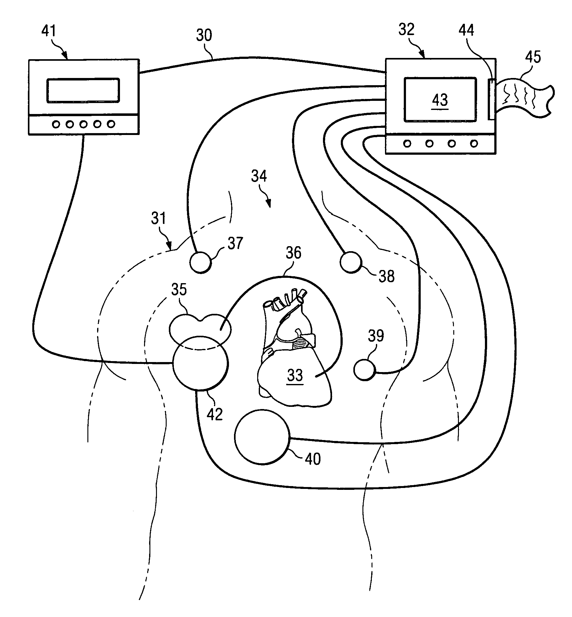
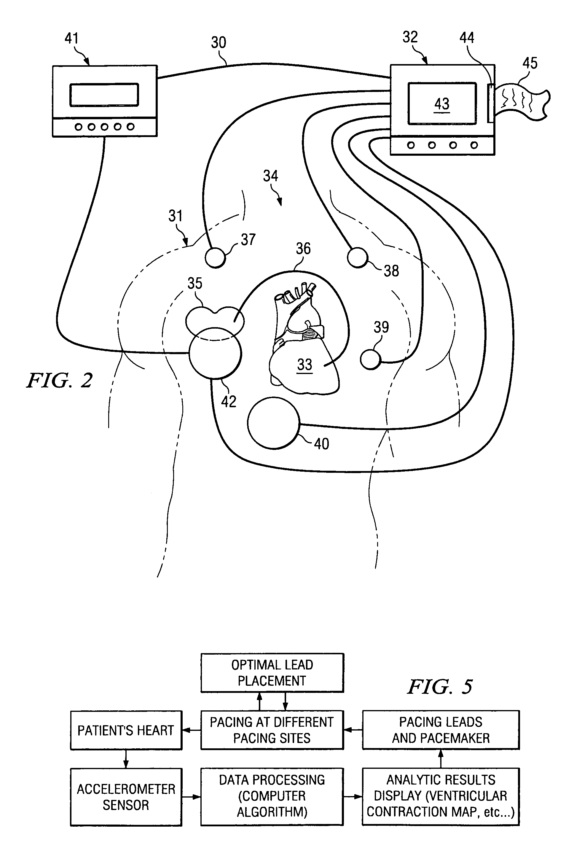
[0030]The invention relates in general to a method for providing a reliable prediction for whether a patient would be a good candidate for cardiac resynchronization therapy and for determining the optimal placement of leads and settings of a cardiac pacing device in real time while the pacing device is implanted into the patient. In one embodiment, the method of the invention preferably includes detecting hemodynamic parameters corresponding to the motion of a patient's heart with an accelerometer, converting the detected parameters into digital data that is fed into an analysis module for calculation and display of ventricular contraction mapping, and comparing the results generated by different pacemaker lead placement to provide an optimal lead location. In another embodiment, hemodynamic parameters are detected and compared to those generated by an unpaced heart, thereby predicting whether CRT is an appropriate option for a given patient.

[0031]The invention further relates to a ...


PUM


Abstract

The patterns of contraction and relaxation of the heart before and during left ventricular or biventricular pacing are analyzed and displayed in real time mode to assist physicians to screen patients for cardiac resynchronization therapy, to set the optimal A-V or right ventricle to left ventricle interval delay, and to select the site(s) of pacing that result in optimal cardiac performance. The system includes an accelerometer sensor; a programmable pace maker, a computer data analysis module, and may also include a 2D and 3D visual graphic display of analytic results, i.e. a Ventricular Contraction Map. A feedback network provides direction for optimal pacing leads placement. The method includes selecting a location to place the leads of a cardiac pacing device, collecting seismocardiographic (SCG) data corresponding to heart motion during paced beats of a patient's heart, determining hemodynamic and electrophysiological parameters based on the SCG data, repeating the preceding steps for another lead placement location, and selecting a lead placement location that provides the best cardiac performance by comparing the calculated hemodynamic and electrophysiological parameters for each different lead placement location.

Description

CROSS REFERENCE TO RELATED APPLICATION[0001]This application claims priority to U.S. Provisional Patent Application Ser. No. 60 / 399,028, which was filed on Jul. 29, 2002 by the same inventors.BACKGROUND OF INVENTION[0002]1. Field of Invention[0003]The present invention relates generally to the implantation of a cardiac pacing device used for cardiac resynchronization therapy (CRT). More specifically, the present invention relates to a realtime method for CRT candidate screening, for optimizing the placement of one or more leads, and for determining optimal settings for cardiac pacing devices.[0004]2. Description of Related Art[0005]Heart failure afflicts about twenty-five million people worldwide, with about two million new cases diagnosed each year. In the United States, hospitalization for heart failure amounts to more than 6.8 million days a year, and the total cost of treatment is more than $38 billion annually, which is increasing as the population ages. The prevalence of conge...

Claims


Application Information

Patent Timeline
Patent Type & Authority Patents(United States)
IPC IPC(8): A61BA61B5/11A61N1/00A61N1/05A61N1/362A61N1/365A61N1/368
CPCA61B5/1107A61N1/3627A61N1/36542A61N1/3682A61N1/3684A61B5/7217A61B5/6869A61N1/36842A61N1/36843
Inventor MARCUS, FRANK I.HE, DING SHENG
Owner HEART FORCE MEDICAL
Why Eureka
Try Eureka