Engine system and method with cylinder deactivation

a technology of cylinder deactivation and engine system, which is applied in the direction of machines/engines, air quality improvement, process and machine control, etc., can solve the problems of increased nox emissions and poor nox conversion efficiency, and achieve the effect of reducing nox emissions, reducing nox emissions, and reducing nox emissions

Active Publication Date: 2005-12-20
FORD GLOBAL TECH LLC
View PDF21 Cites 135 Cited by
  • Summary
  • Abstract
  • Description
  • Claims
  • Application Information

AI Technical Summary

Benefits of technology

[0002]However, the inventors herein have recognized that it can also be advantageous to operate in some conditions with all of the cylinder pumping air without fuel injection, especially in tip-out conditions where the vehicle operator has tipped-out of the vehicle accelerator pedal.
[0004]By commencing combustion at a lean air-fuel ratio after operating in the fuel cut operation, it is possible to retain a lean exhaust mixture air-fuel so that any NOx generated can be stored in an emission control device capable of lean NOx storage. Further, lean combustion upon re-enabling combustion provides for greater variety of torque levels, especially when a group of cylinders is re-enabled. In other words, it is possible to provide accurate control of low, or negative, torque levels during engine deceleration conditions, such as during driver tip-out conditions.
[0005]In other words, full cylinder cut operation can be done with minimal NOx emissions impact since the NOx trap can operated even in an excessively oxidized state. When the cylinder cut phase is completed, the engine can be operated in a lean-burn mode. The NOx trap retains any NOx from the cylinder re-enablement thereby reducing NOx emissions. Further, the engine can be cycled between lean operation and cylinder cut operation without emissions impact. In addition, the NOx trap, and any three way catalysts in the system, can be regenerated when the NOx trap is filled with NOx or when lean operation is no longer requested. This leads to reduced regenerations of the exhaust system, further improving fuel economy performance.BRIEF

Problems solved by technology

This can cause increased NOx emissions when the engine is restarted, since any NOx generated during the cylinder start will not be efficiently converted in an oxidized exhaust system due to the fact that any three way catalyst present generally have poor NOx conversion efficiency in a completely oxidized state or in lean exhaust.

Method used


Image

  • Engine system and method with cylinder deactivation
  • Engine system and method with cylinder deactivation
  • Engine system and method with cylinder deactivation

Examples


Embodiment Construction

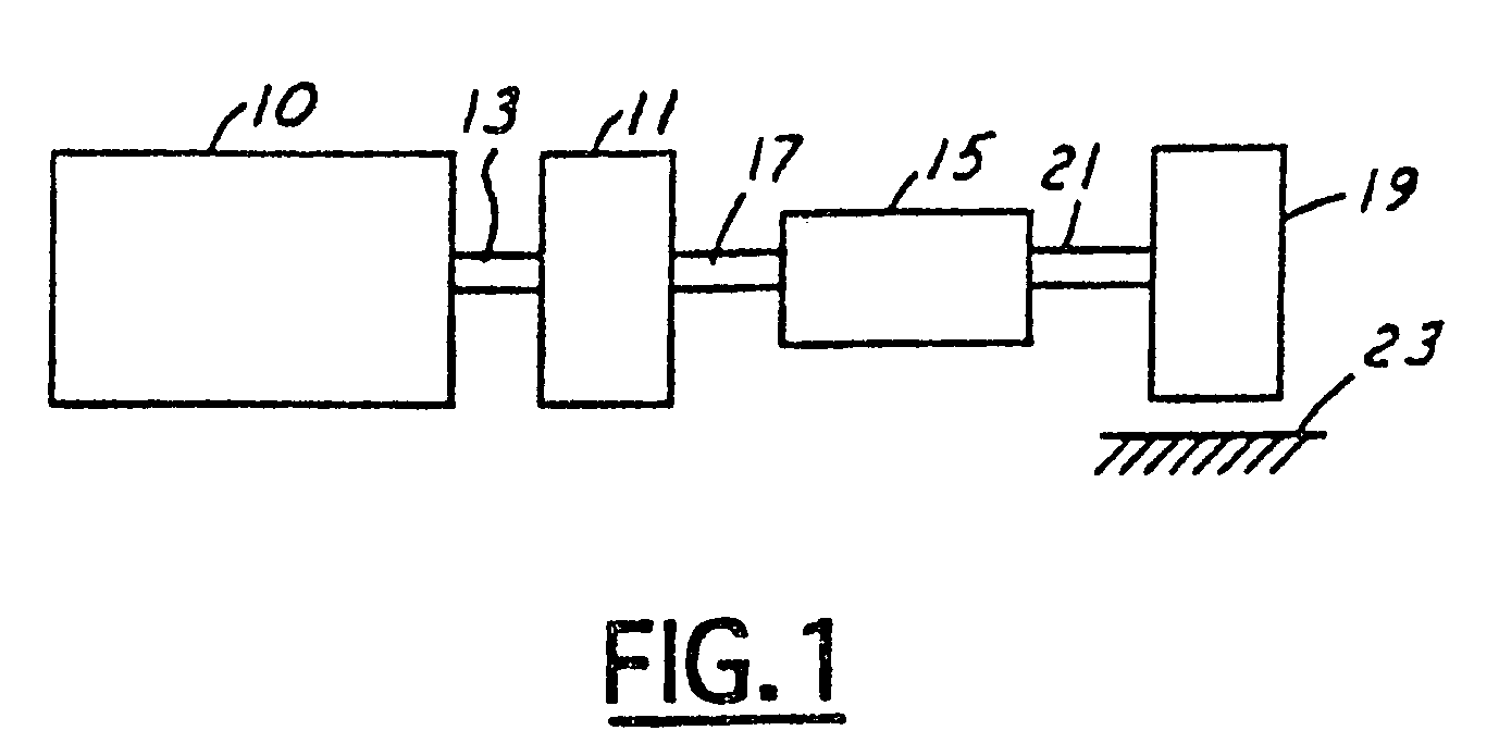
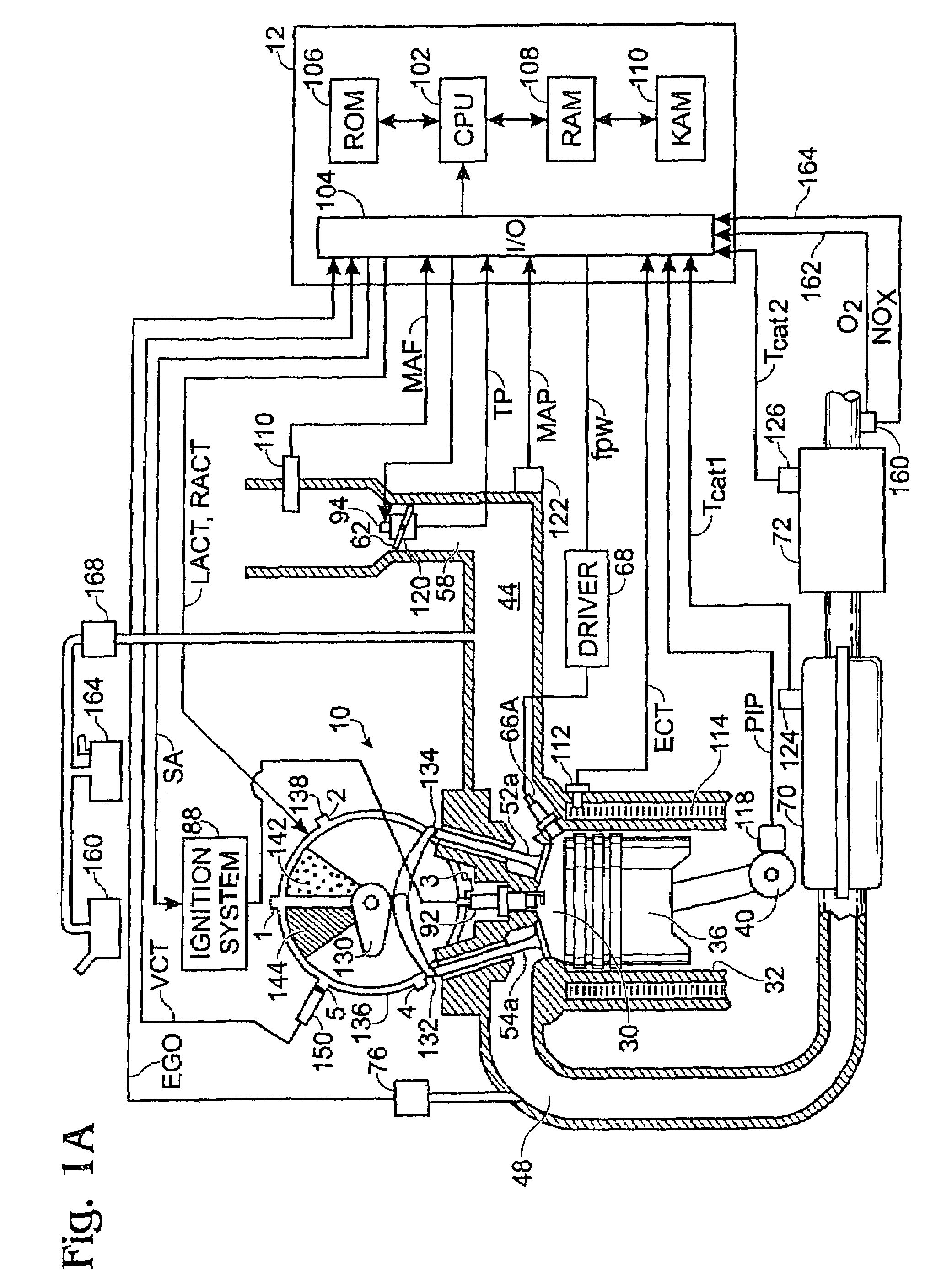
[0017]Referring to FIG. 1, internal combustion engine 10, further described herein with particular reference to FIGS. 1A and 1B, is shown coupled to torque converter 11 via crankshaft 13. Torque converter 11 is also coupled to transmission 15 via turbine shaft 17. Torque converter 11 has a bypass, or lock-up clutch 14 which can be engaged, disengaged, or partially engaged. When the clutch is either disengaged or partially engaged, the torque converter is said to be in an unlocked state. The lock-up clutch 14 can be actuated electrically, hydraulically, or electro-hydraulically, for example. The lock-up clutch 14 receives a control signal (not shown) from the controller, described in more detail below. The control signal may be a pulse width modulated signal to engage, partially engage, and disengage, the clutch based on engine, vehicle, and / or transmission operating conditions. Turbine shaft 17 is also known as transmission input shaft. Transmission 15 comprises an electronically co...


PUM


Abstract

Various systems and methods are disclosed for carrying out combustion in a fuel-cut operation in some or all of the engine cylinders of a vehicle. Further, various subsystems are considered, such as fuel vapor purging, air-fuel ratio control, engine torque control, catalyst design, and exhaust system design.

Description

BACKGROUND AND SUMMARY[0001]Engines are usually designed with the ability to deliver a peak output, although most engine operation is performed well below this peak value. As such, it can be beneficial to operate with some cylinders inducting air without fuel injection as described in U.S. Pat. No. 6,568,177.[0002]However, the inventors herein have recognized that it can also be advantageous to operate in some conditions with all of the cylinder pumping air without fuel injection, especially in tip-out conditions where the vehicle operator has tipped-out of the vehicle accelerator pedal.[0003]Further, the inventors herein have recognized that when the all of the cylinders are in the fuel shut-off condition, air (still being pumped by the engine) oxidizes the whole catalyst system in the exhaust. This can cause increased NOx emissions when the engine is restarted, since any NOx generated during the cylinder start will not be efficiently converted in an oxidized exhaust system due to ...

Claims


Application Information

Patent Timeline
Patent Type & Authority Patents(United States)
IPC IPC(8): F01N9/00F02D41/04G06F17/00
CPCF02P5/1504F02M25/089F02D17/02F01N3/027F02D41/0087F02D41/0235F02D41/126F02P5/045F01N3/0814F01N3/0842F01N3/101F01N13/107F02D41/022F02D41/0275F02D41/064F02D41/065F02D41/086F02D41/182F02D41/0042F02D41/0045F02D2041/001F02D2200/0802F02D2200/602Y02T10/46Y02T10/22Y02A50/20Y02T10/12Y02T10/40
Inventor SURNILLA, GOPICHANDRABIDNER, DAVIDELWART, SHANEDOERING, JEFFGORALSKI, JR., CHRISTIAN T.
Owner FORD GLOBAL TECH LLC
Why Eureka
Try Eureka