
Mower bed blade method

a mower bed and blade technology, applied in the field of mower bed blades, can solve the problems of requiring replacement, sharpening and removing the mower blades, requiring a lot of time, energy and expense, and often cracking or chipping along the lateral edges, so as to achieve the effect of rarely chipping or cracking

Inactive Publication Date: 2005-12-27
JRM
View PDF13 Cites 9 Cited by
  • Summary
  • Abstract
  • Description
  • Claims
  • Application Information

AI Technical Summary

Benefits of technology

"The patent describes a manufacturing process for mower bed blades, specifically for golf greens. The process involves selecting a suitable coil of flat steel, punching mounting holes in the steel, coining the steel to form the cutting edge, shearing the blade to remove excess metal, machining the blade to form clearance angles, heat treating the blade, and using grinders to sharpen the cutting edge. The resulting blades are uniform, durable, and require less frequent sharpening."

Problems solved by technology

Removing, sharpening and replacing the mower blades requires much time, energy and expense.
In critical mowing times as during golf tournaments, the time and energy spent can be very costly and exacting.
Such blades often crack or chip along the lateral edges and must be replaced.
Conventional blades are also likely to crack or distort when impacted by a rock along the cutting edge.
During manufacturing, milling or machining with a conventional CNC machine at one location on the blade may take 4–5 minutes, which greatly adds to the blade cost.
Further, many conventional mower bed blades are made by stamping, however dies are not used and the stamped blanks are not uniform and can slightly vary in shape and size.
This nonuniformity requires additional manufacturing steps which adds to the blade cost and expense.

Method used


Image

  • Mower bed blade method
  • Mower bed blade method
  • Mower bed blade method

Examples


Embodiment Construction

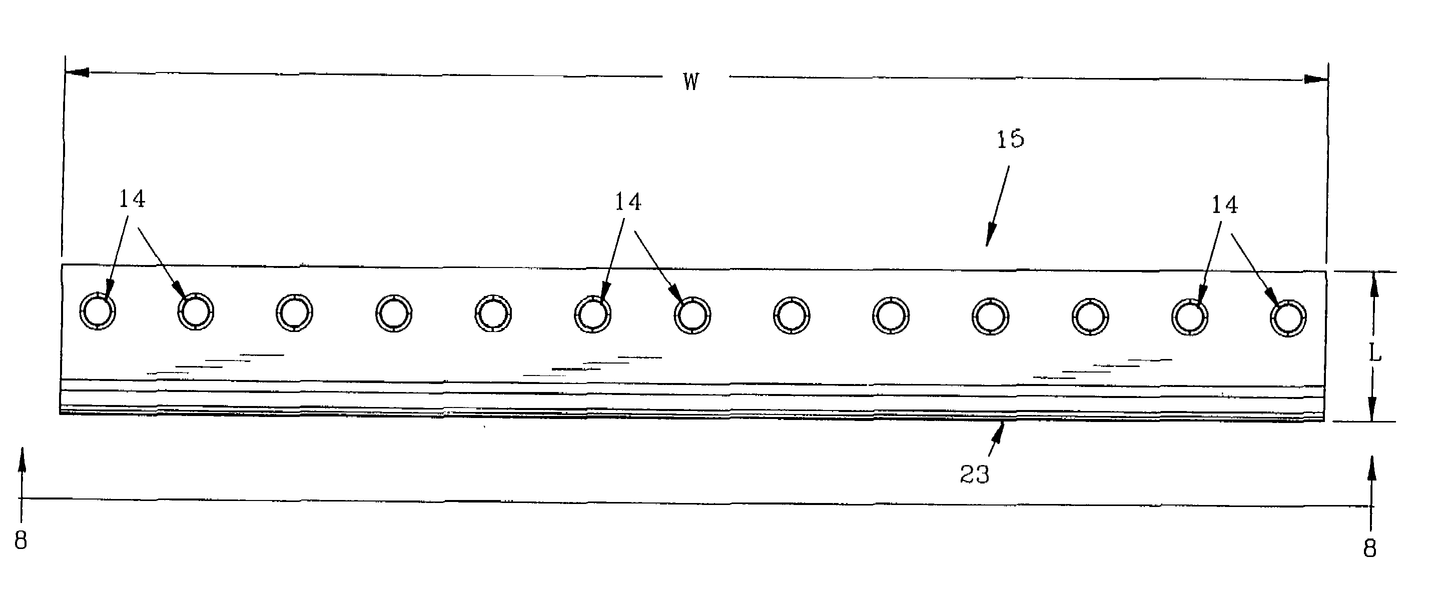
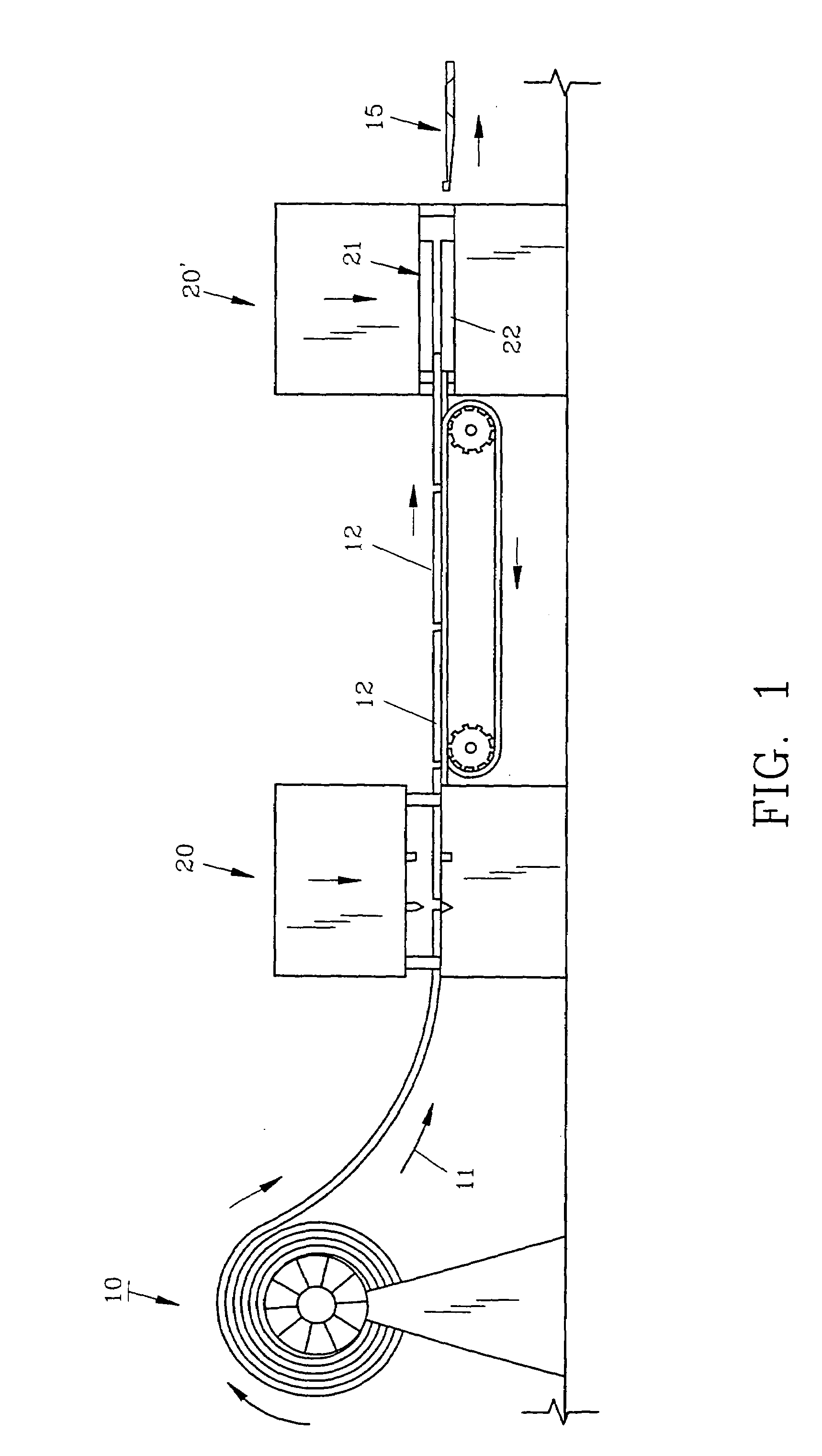
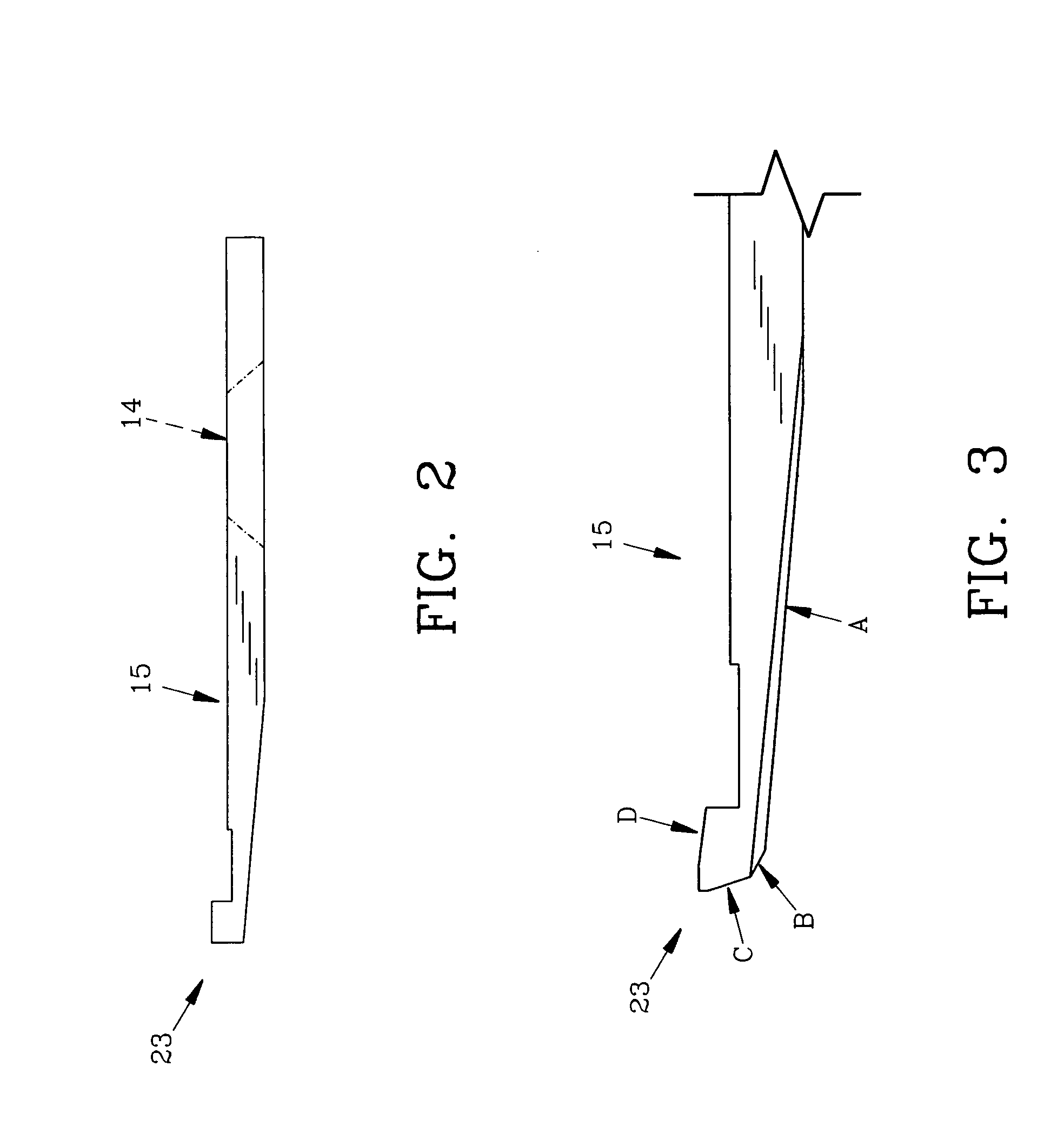
[0029]For a better understanding of the invention and its operation, turning now to the drawings, FIG. 1 shows in schematic representation certain steps of the preferred process for manufacturing mower bed blades. Coil 10 of preferably, grade 1566 (AISI-SAE1566) flat steel (UNS No. 615,660) having a carbon (c) content of; 0.60–0.71%; manganese (mn) 0.85–1.15%; phosphorous (p) 0.040% and sulfur (s) 0.050% is utilized. While other steels can be used, this particular alloy is preferred. Steel coil 10 has a width of 21.75 inches (552.45 mm) and a thickness of 0.134 inches (3.3 mm) with the grain running in the direction of the length of the coil as indicated by arrow 11. Dake hydraulic press 20 as manufactured by Dake, division of JSJ Corporation of 724 Robbins Road, Grand Haven, Mich. 49417, having a capacity of 400 tons, shears the leading edge of coil 10 into blade blanks 12 measuring 2.5 inches (63.5 mm) long (not shown to scale in FIG. 1). Press 20 cuts coil 10 into blanks 12 using...


PUM

PropertyMeasurementUnit
angleaaaaaaaaaa
temperatureaaaaaaaaaa

Abstract

A method of forming a durable mower bed blade is provided in which the grain of the metal is perpendicular to the longitudinal axis of the blade. The blade is formed in part by coining the blade on a hydraulic press which strengthens the cutting edge and other areas to prevent chipping and cracking. Additional steps in the process include shearing the blade to a proper width, heat treating and grinding the edge of the blade to sharpen it.

Description

FIELD OF THE INVENTION[0001]The invention herein pertains to a method for forming a blade for a grass mower and particularly pertains to forming a bed blade for a mower as used for cutting golf greens.DESCRIPTION OF THE PRIOR ART AND OBJECTIVES OF THE INVENTION[0002]Grass mowers of the reel type conventionally use a lower or “bed” blade which in combination with the reel blades cuts grass to a high or exact tolerance. Golf greens which are cut once or more daily require very sharp blades and it is not unusual for a greens keeper to cut only two or three greens before having to remove the blades from the mower and sharpen them to ensure a smooth, close, even cut for the next green. Removing, sharpening and replacing the mower blades requires much time, energy and expense. In critical mowing times as during golf tournaments, the time and energy spent can be very costly and exacting.[0003]Conventional bed blades are generally formed by stamping metal blanks and sharpening the blanks to...

Claims


Application Information

Patent Timeline
Patent Type & Authority Patents(United States)
IPC IPC(8): B21D53/64B21K5/12B21K11/00B23P13/04B23P15/40
CPCB23P15/40B21D53/647B21K5/12B21K11/00Y10T29/49995Y10T29/49996Y10T29/49798
Inventor MERRITT, JAMES R.
Owner JRM
Learn More