High capacity microarray dispensing

Inactive Publication Date: 2005-12-27
AGENA BIOSCI
View PDF50 Cites 32 Cited by
  • Summary
  • Abstract
  • Description
  • Claims
  • Application Information

AI Technical Summary

Benefits of technology

[0010]The present invention provides a high capacity microarrayer for spotting solution onto slides in an automated microarray dispensing device. A microplate indexing device automatically moves, in sequence, a plurality of microplates to a solution removal area. A dispense head accesses each microplate at the solution removal area to remove solution from the microplate. The dispense head then moves to a slide positioning station to spot slides at the slide positioning station. In a preferred embodiment of the present invention, the microplate indexing station has at least one input stacking chamber for stacking microplates, and at least one output stacking chamber for stacking microplates. A walking beam indexer is disposed between the at least one input stacking chamber and the at least one output stacking chamber. The walking beam indexer is for moving microplates from said at least one input stacking chamber to said at least one output stacking chamber. While at the solution removal area, a lid lifter lifts the lid off each microplate to permit the microplate to be accessed by the dispense head for solution removal. After the solution is removed, the lid lifter replaces the lid. In another preferred embodiment

Problems solved by technology

However, there are significant problems with the prior art devices that detracts from their efficient operation.
A first problem arises due to the fact that as blank slides are cycled through prior art microarrayers, they can become askew or positioned improperly underneath dispensing tips.
This problem results in spots being positioned improperly on the slides.
A second problem can arise even if the slide is positioned correctly under the dispensing tips.
It is possible for the spot to be dep

Method used


Image

  • High capacity microarray dispensing
  • High capacity microarray dispensing
  • High capacity microarray dispensing

Examples


first preferred embodiment

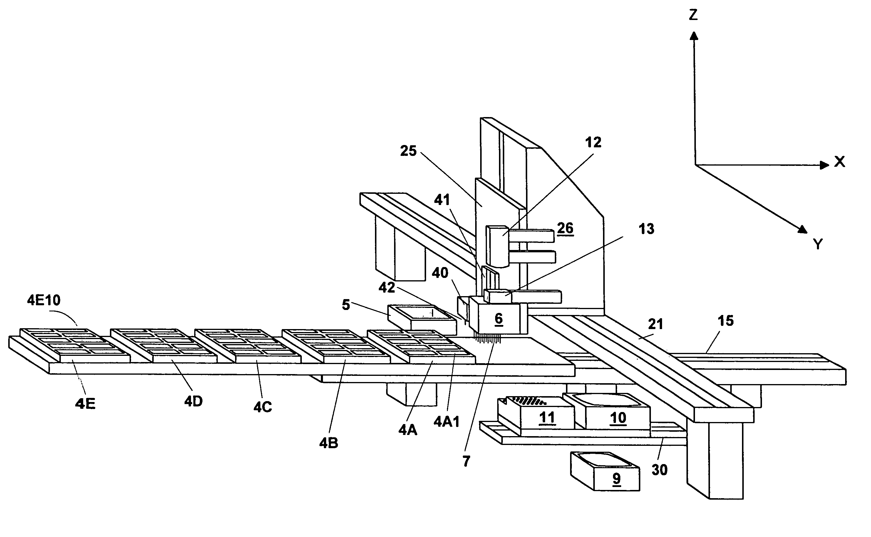
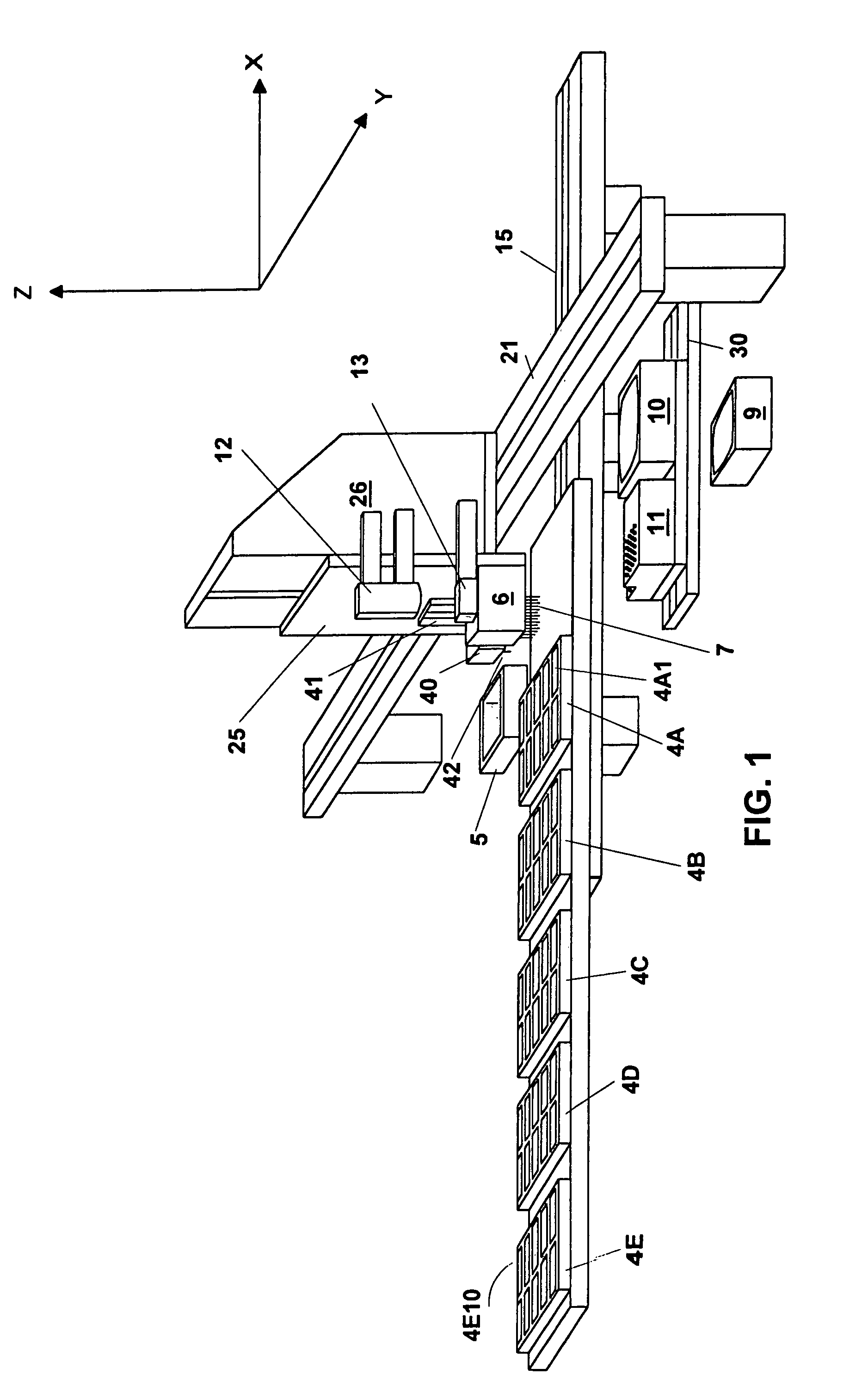
[0037]A detailed description of a first preferred embodiment of the present invention can be described by reference to FIGS. 1–38B. During the operation of the present invention, solution from reservoir plate 5 is automatically deposited onto an array of fifty blank slides 4A1–4E10 located on locating plates 4A–4E (see FIG. 1). An operator is able to select via a computer interface whether dispense tip 42 (located underneath dispense head 40) or a 4×6 array of dispense tips 7 (located underneath dispense head 6) will be used to make the deposits onto slides 4A1–4E10. In the preferred embodiment, dispense tips 7 and 42 are quill type dispense tips. Locating plates 4A–4E are mounted on linear actuator 15 so that they can move along the x-axis. Linear actuator 26 is mounted on linear actuator 21 so that linear actuator 26 can move along the y-axis. Dispense heads 6 and 40 are mounted on linear actuator 26 so that they can move along the z-axis. Camera 12 with strobe light 13 is focused...

third preferred embodiment

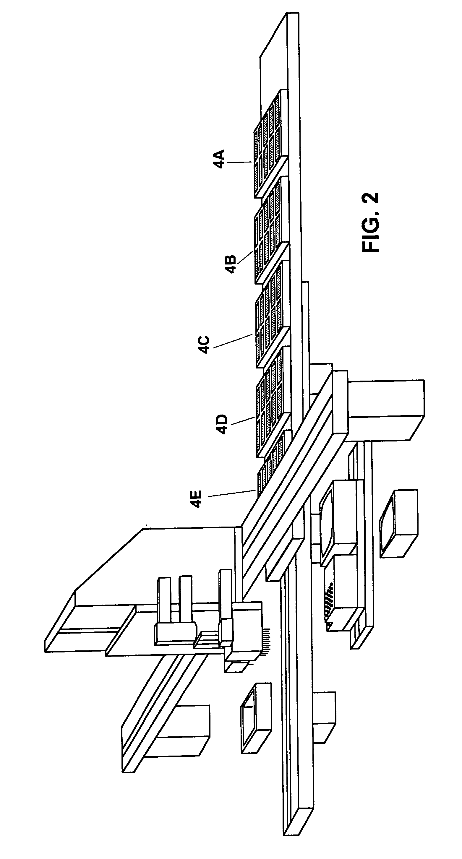
[0095]A perspective view of the third preferred embodiment is seen by reference to FIG. 42. The third preferred embodiment is similar to the second preferred embodiment in that it has the advantage of accommodating high capacity microplate handling capabilities. The third preferred embodiment of the present invention utilizes microplate indexing station 700, also shown in FIGS. 44A and 44B. Embodiments of microplate indexing station 700 were described in detail in U.S. application Ser. No. 09 / 411,943, the specification of which is herein incorporated by reference. In U.S. application Ser. No. 09 / 411,943, microplate indexing station 700 was described as being used in conjunction with an automated microplate filling device and it included a microplate fill nozzle. In the third preferred embodiment of the present invention, microplate indexing station 700 is used in conjunction with other components to dispense solution onto slides.

Overview of the Operation of the Third Preferred Embod...


PUM


Abstract

A high capacity microarrayer for spotting solution onto slides in an automated microarray dispensing device. A microplate indexing device automatically moves, in sequence, a plurality of microplates to a solution removal area. A dispense head accesses each microplate at the solution removal area to remove solution from the microplate. The dispense head then moves to a slide positioning station to spot slides at the slide positioning station. In a preferred embodiment of the present invention, the microplate indexing station has at least one input stacking chamber for stacking microplates, and at least one output stacking chamber for stacking microplates. A walking beam indexer is disposed between the at least one input stacking chamber and the at least one output stacking chamber. The walking beam indexer is for moving microplates from said at least one input stacking chamber to said at least one output stacking chamber. While at the solution removal area, a lid lifter lifts the lid off each microplate to permit the microplate to be accessed by the dispense head for solution removal. After the solution is removed, the lid lifter replaces the lid. In another preferred embodiment, there is at least one light source capable of illuminating the slides, and at least one camera operating in conjunction with the at least one light source. The at least one camera is capable of acquiring and transmitting slide image data to a computer. The computer is programmed to receive the slide image and analyze it. The computer will then generate post analysis data based on the analysis of the slide image data. The post analysis data is available for improving the spotting of the solution onto the slides. In a preferred embodiment, the slide image data includes information relating to slide alignment, information relating to spot quality, and slide identification information. In a preferred embodiment, the analysis of the information relating to slide alignment enables the computer to make automatic adjustments to the relative positions of the at least one dispense head and the slides to increase the accuracy of the spotting. In a preferred embodiment, the analysis of the information relating to spot quality identifies a spot as pass or fail. An operator is then able to rework the spot. In a preferred embodiment, the analysis of the slide identification information enables the computer to track each slide.

Description

[0001]The present invention relates to automated microarray dispensing devices, more specifically it relates to high capacity automated microarray dispensing devices. The present invention is a continuation-in-part of U.S. patent application Ser. No. 09 / 411,943, filed Oct. 4, 1999, now U.S. Pat. No. 6,148,878, and is also a continuation-in-part of U.S. patent application Ser. No. 09 / 611,256, filed Jul. 6, 2000.BACKGROUND OF THE INVENTION[0002]Microarrays, also known as biochips, have recently become important in the study of genomics. The use of a microarray involves laying down an ordered array of genetic elements onto a solid substrate such as a slide. Depending on the application, a microarray may consist of genomic DNA, reverse-transcribed cDNA, or smaller chains of oligonucleotides as well as any preparatory substrates. The microarray is useful because it allows genetic analysis to take place on a massively parallel scale, wherein thousands of genes and markers can be scored in...

Claims


Application Information

Patent Timeline
IPC IPC(8): B01J19/00B01L3/02G01N15/06G01N21/00G01N21/29G01N35/00G01N35/04
CPCB01J19/0046B01J2219/00364B01J2219/00387B01J2219/00531B01J2219/00659B01J2219/00691Y10T436/112499B01J2219/00722B01L3/0244G01N2035/00158G01N2035/0422Y10T436/114998Y10T436/2575B01J2219/00693
Inventor GANZ, BRIAN L.MICKLEY, MANDEL W.MOULDS, JOHN ANDREWBROVOLD, CHRITOPHER T.
Owner AGENA BIOSCI
Why Eureka
Try Eureka