Oscillator circuit with temperature compensation function

a technology of oscillator circuit and function, which is applied in the direction of oscillator generator, pulse automatic control, angle modulation details, etc., can solve the problems of inability to accommodate the variations of oscillation frequency, and the accommodation of the device characteristic in the narrow oscillation frequency band at the time of power supply voltage about 1v is considered to be almost impossibl

Inactive Publication Date: 2005-12-27
LAPIS SEMICON CO LTD
View PDF1 Cites 23 Cited by
  • Summary
  • Abstract
  • Description
  • Claims
  • Application Information

AI Technical Summary

Benefits of technology

[0009]In the oscillator circuit according to the present invention, the temperature compensation data based on the temperature of the oscillator circuit is generated by the temperature detector during the operation of the oscillator circuit. Further, the capacitances of the temperature compensating capacitors are adjusted to adjust the capacitance value of the resonant circuit, whereby temperature-compensation for an oscillation frequency range of the oscillator circuit is carried out. According to the oscillator circuit having such a configuration, even if a drive voltage is low and the oscillation frequency is narrow in variable width, the influence of the temperature on the oscillation frequency can be compensated and a required oscillation frequency band can be ensured.

Problems solved by technology

That is, the oscillator circuit or a voltage-controlled oscillator becomes narrow in oscillation frequency band when its drive voltage is reduced, and cannot afford to accommodate variations in oscillation frequency due to a change in temperature in terms of the frequency.
Further, when the variations in production device characteristic are taken into consideration, the accommodation of the variations in device characteristic in the narrow oscillation frequency band at the time that the power supply voltage is about 1V is considered to be almost impossible.

Method used


Image

  • Oscillator circuit with temperature compensation function
  • Oscillator circuit with temperature compensation function
  • Oscillator circuit with temperature compensation function

Examples


Embodiment Construction

[0026]Preferred embodiments of the present invention will hereinafter be described in detail with reference to the accompanying drawings.

[Overall Configuration]

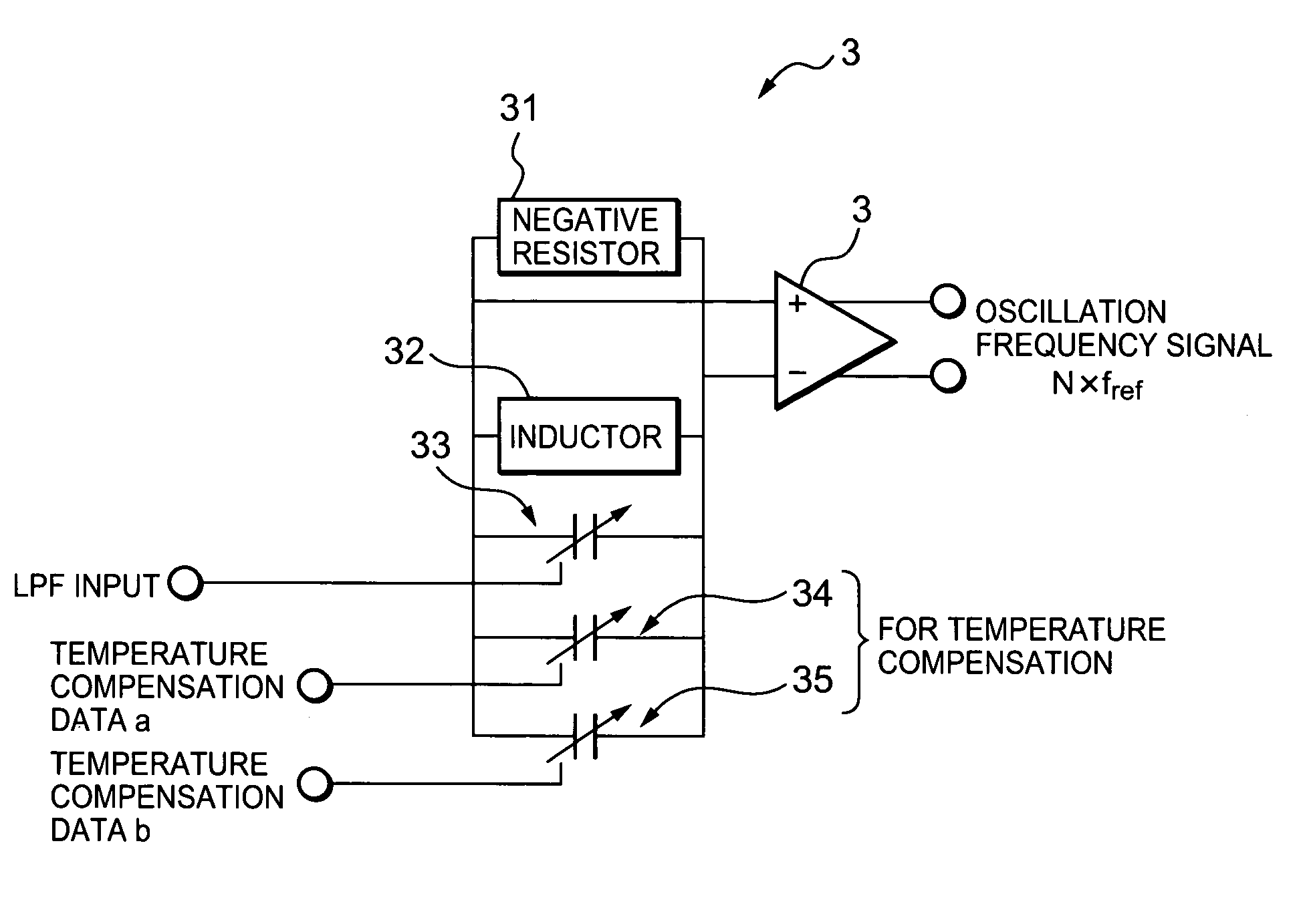
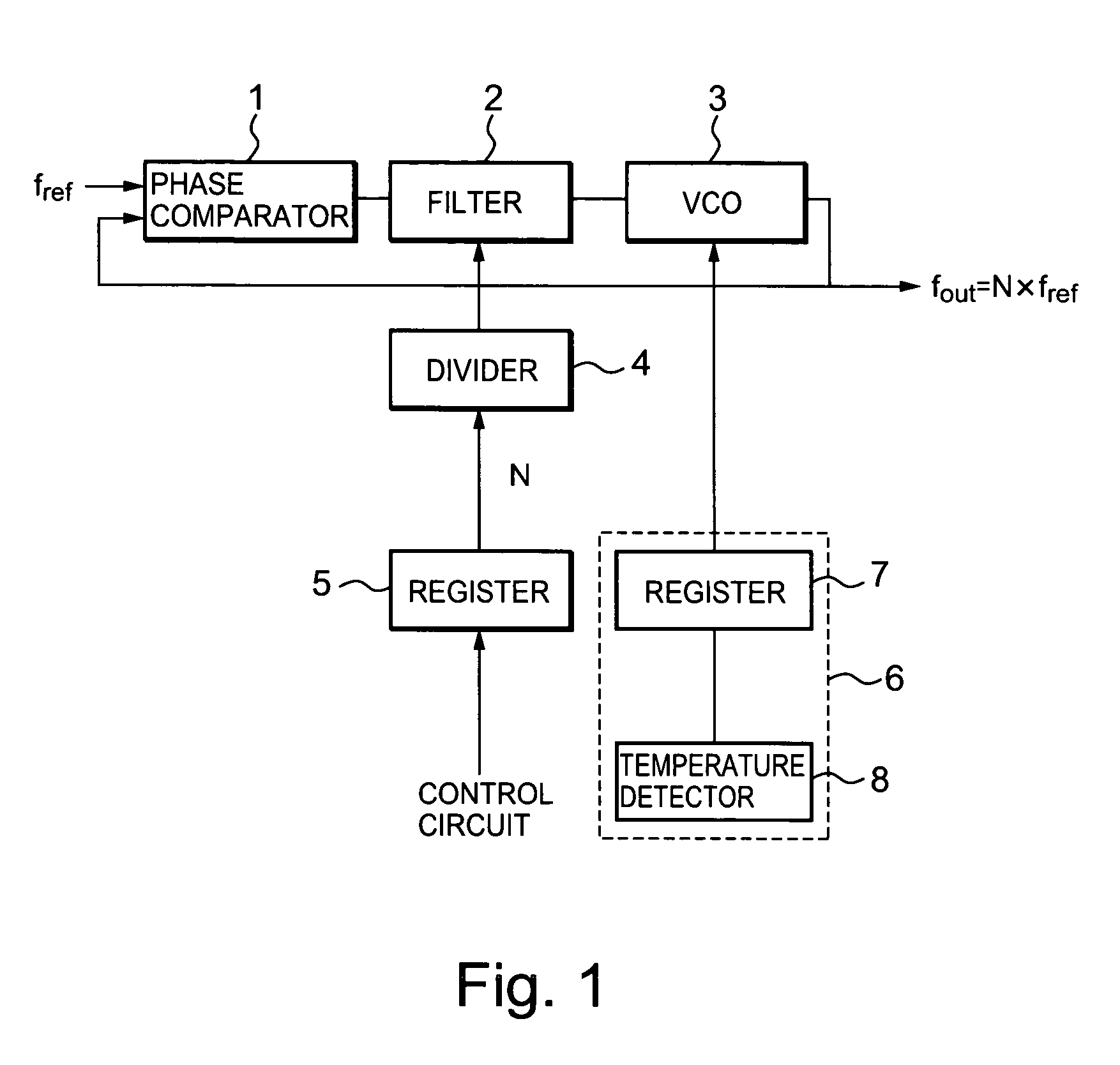
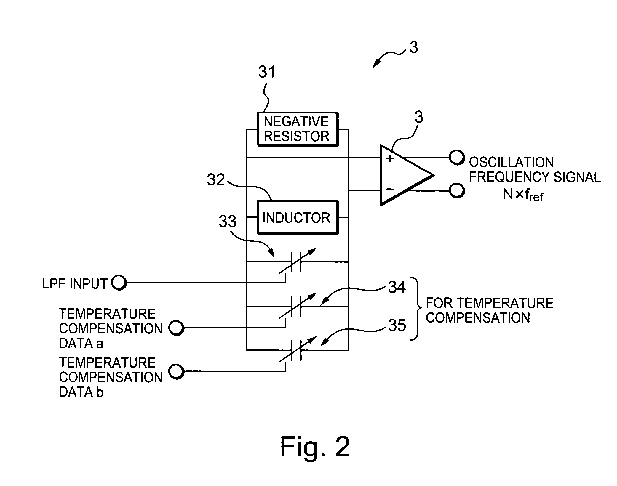
[0027]FIG. 1 is a configurational example of an oscillator circuit 100 according to a first embodiment. The oscillator circuit 100 is contained in a wireless integrated circuit mounted in a wireless apparatus such as a wireless local area network (LAN) and determines a carrier frequency of a radio wave in accordance with the oscillation frequency of an output signal of the oscillator circuit 100.

[0028]The oscillator circuit 100 is a phase locked loop type oscillator circuit, for example. As will be described later, the oscillator circuit 100 has a temperature compensating function for compensating for the influence of a change in the temperature of the oscillator circuit 100 on an oscillation frequency band.

[0029]The oscillator circuit 100 includes a phase locked loop comprising a phase comparator 1, a loop filter 2, a voltag...


PUM


Abstract

An oscillator circuit comprising a resonant circuit which includes a negative resistor, an inductor and an oscillation frequency setting capacitor whose capacitance is varied according to a control voltage based on oscillation frequency data and which outputs a signal having an oscillation frequency based on the oscillation frequency data, a temperature detector which outputs temperature compensation data, based on the temperature, and temperature compensating capacitors which are electrically connected to the resonant circuit and which are supplied with the temperature compensation data to change capacitance values thereof based on the temperature compensation data, thereby adjusting the oscillation frequency.

Description

BACKGROUND OF THE INVENTION[0001]The present invention relates to an oscillator circuit and a control method thereof, and particularly to an oscillator circuit driven at a low voltage and a control method thereof.[0002]A high-frequency oscillator circuit is configured of, for example, a resonant circuit in which a negative resistor, an inductor and a variable capacitance type capacitor are parallel-connected to one another. A method of controlling the oscillation frequency of such an oscillator circuit is carried out by changing the capacitance of the capacitor with a voltage or changing the mutual conductance of the negative resistor with current as described in the following non-patent document 1, for example. A field effect transistor is generally used as the variable capacitance type capacitor. Described specifically, a gate electrode of the field effect transistor is connected to the negative resistor and the inductor, and a source electrode and a drain electrode thereof are sh...

Claims


Application Information

Patent Timeline
Patent Type & Authority Patents(United States)
IPC IPC(8): H03B5/04H03B5/08H03B5/12H03K3/26H03L1/02H03L7/099H03L7/18
CPCH03B5/04H03L1/023H03L7/099H03L7/18
Inventor FUJITA, KEN
Owner LAPIS SEMICON CO LTD
Why Eureka
Try Eureka