Arc detection apparatus and method

a detection apparatus and arc technology, applied in the field of electric circuits, can solve the problems of low signal processing efficiency, high cost, and high cost of all three approaches, and achieve the effect of low cost and simplified signal processing

Inactive Publication Date: 2005-12-27
SENSATA TECH MASSACHUSETTS INC
View PDF10 Cites 19 Cited by
  • Summary
  • Abstract
  • Description
  • Claims
  • Application Information

AI Technical Summary

Benefits of technology

[0010]This provides the ability to measure charge from the transformer over a wide dynamic range. The log function also simplifies signal processing and enables the use of a relatively low cost microcontroller rather than a digital signal processor typically used in prior art techniques.

Problems solved by technology

However, the McEachern et al. and Baxter et al. comparison signals suffer from nuisance tripping caused by varying loads.
All three approaches require relatively costly, power-hungry, fast digital processing because a plurality of points per cycle need to be sampled.

Method used


Image

  • Arc detection apparatus and method
  • Arc detection apparatus and method
  • Arc detection apparatus and method

Examples


Embodiment Construction

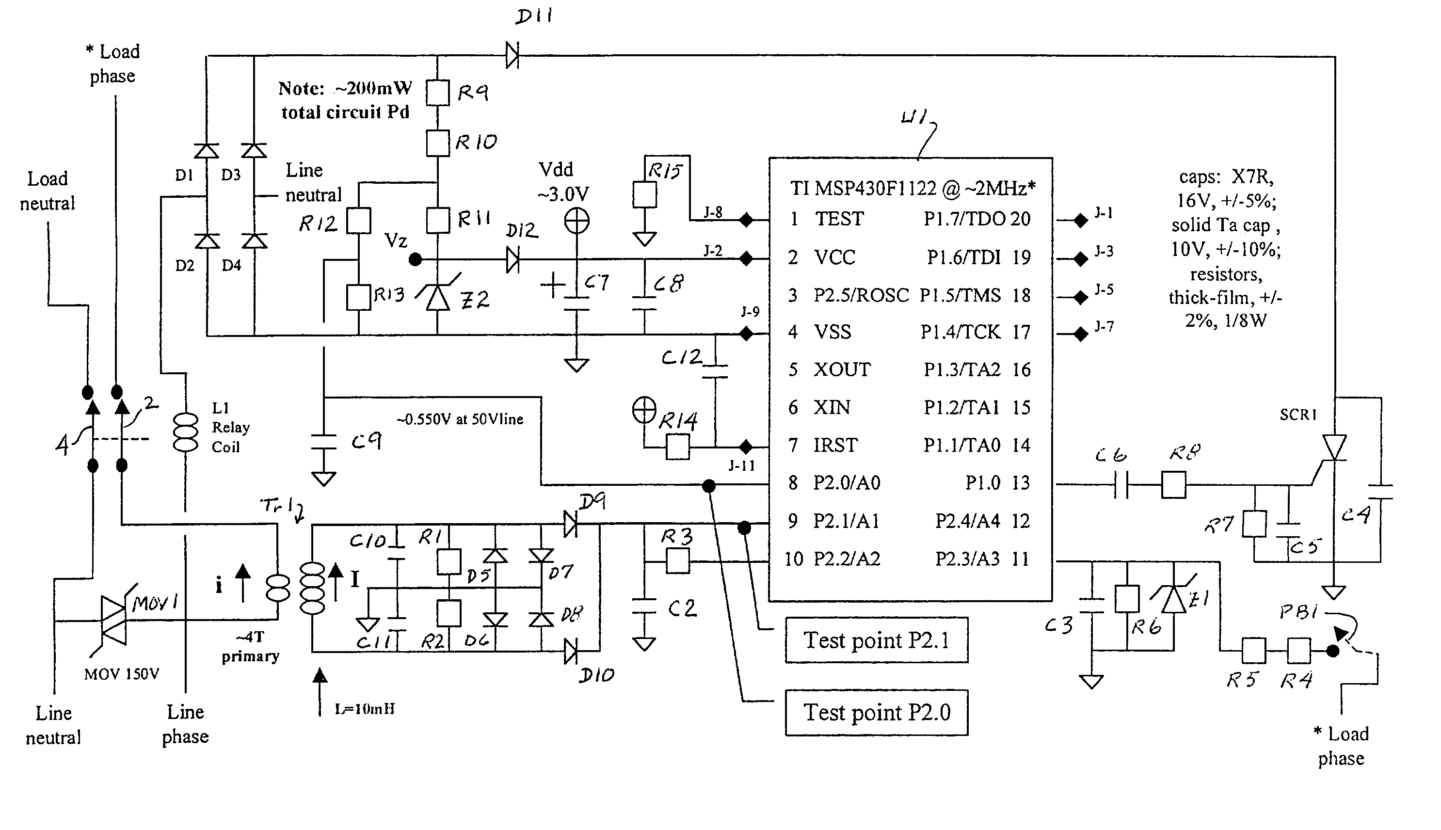
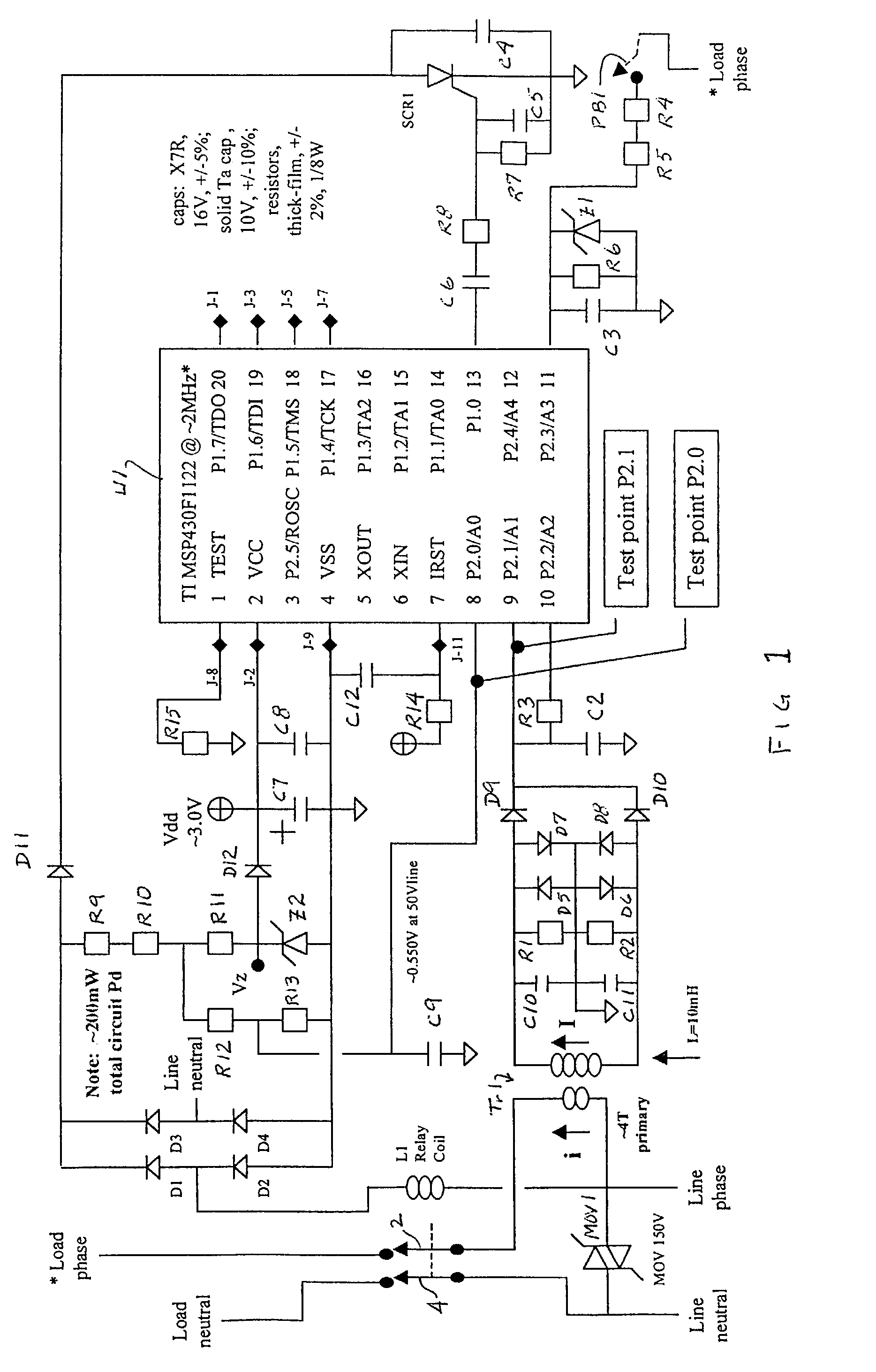
[0020]With reference to FIG. 1, relay coil L1 is connected to line phase and is arranged to control the state of energization of main contacts 2, 4 which either connect or separate the main line neutral and line phase to or from the load neutral and load phase line, respectively. Normally, power in the coil is low enough that the relay contacts remain closed. When SCR1 is turned on, however, as will be described, current increases in the relay coil to open the contacts. Metal oxide varistor MOV1 is connected between line neutral and line phase to prevent excessive line voltage.

[0021]Current flowing through a load is monitored by a transformer Tr1 comprising roughly three turns of a primary coil and several hundred turns of a weakly coupled secondary coil, that is, a coupling having low mutual inductance on the order of 20–50 micro Henrys, in order to transfer high frequency components of the primary current to the monitoring circuit. The secondary current is rectified and fed to a l...


PUM


Abstract

Current flowing through a load is monitored by a transformer (Tr1) having a small mutual inductance. The secondary coil is shorted through a rectifier circuit to deliver a charge which, in a first preferred embodiment, is connected to a log charge translator circuit comprising matching diodes (D9, D7 and D10, D8) and a capacitor (C2) to provide a capacitor voltage proportional to the log of the charge delivered through the rectifier circuit. The capacitor is reset after each measurement. In a modified embodiment, the log translator circuit comprises a pair of transistors (T1, T2) and a capacitor (C2). According to the preferred embodiments, two measurements of the capacitor voltage are taken each half cycle at a time determined by the absolute value of the line voltage. The measurements per half cycle are stored in words in a stack and processed through a three or five cycle algorithm for determining fluctuations which will cancel out disturbances caused by nuisance loads that are repetitive or continuously varying. In a described embodiment, a pushdown stack of 60 words is used with fluctuations compared by a microcontroller to a selected limit. Measurements for the last half second of measurements are considered, ignoring the first and last measurement, and when the sum of the fluctuations exceeds the selected limit an arc is indicated and a circuit interrupter is tripped. A self test button is connected to the microcontroller which, when depressed, results in charging of the capacitor to stimulate the detection of an arc.

Description

FIELD OF THE INVENTION[0001]This invention relates generally to electrical circuits and more particularly to the detection of arcs and to the tripping of a circuit interrupter upon the detection of such arcs.BACKGROUND OF THE INVENTION[0002]Arc detection on alternating current (AC) power lines are known in the art. Examples of prior art detectors include U.S. Pat. No. 4,694,402 to McEachern et al.; U.S. Pat. No. 5,229,651 to Baxter et al. and U.S. Pat. No. 5,452,223 to Zuercher et al. McEachern et al. teach the comparison of adjacent cycles to detect waveform disturbances. Baxter et al. teach the comparison of the current cycle to a reference cycle built up from many prior cycles and Zuercher et al. teach the use of cumulative difference signals at predetermined points over many cycles to detect arcs. However, the McEachern et al. and Baxter et al. comparison signals suffer from nuisance tripping caused by varying loads. This limitation is addressed in Zuercher et al. by further ana...

Claims


Application Information

Patent Timeline
Patent Type & Authority Patents(United States)
IPC IPC(8): H02H3/22H01H83/02H01H83/04H01H83/20H02H1/00H02H1/04H02H3/50
CPCH02H1/0015H02H1/04
Inventor KAWATE, KEITH W.PELLON, CHRISTIAN V.
Owner SENSATA TECH MASSACHUSETTS INC
Why Eureka
Try Eureka