
Multiple access spread spectrum switching methodology

a spread spectrum and switching methodology technology, applied in the direction of sustainable communication technology, high-level techniques, climate sustainability, etc., can solve the problem of keeping switching equipment costs a minimum, achieve the effect of minimizing the complexity of the switching fabric, high performance and reducing the cost of switching equipmen

Inactive Publication Date: 2005-12-27
AMERICAN TELEPHONE & TELEGRAPH CO
View PDF15 Cites 29 Cited by
  • Summary
  • Abstract
  • Description
  • Claims
  • Application Information

AI Technical Summary

Benefits of technology

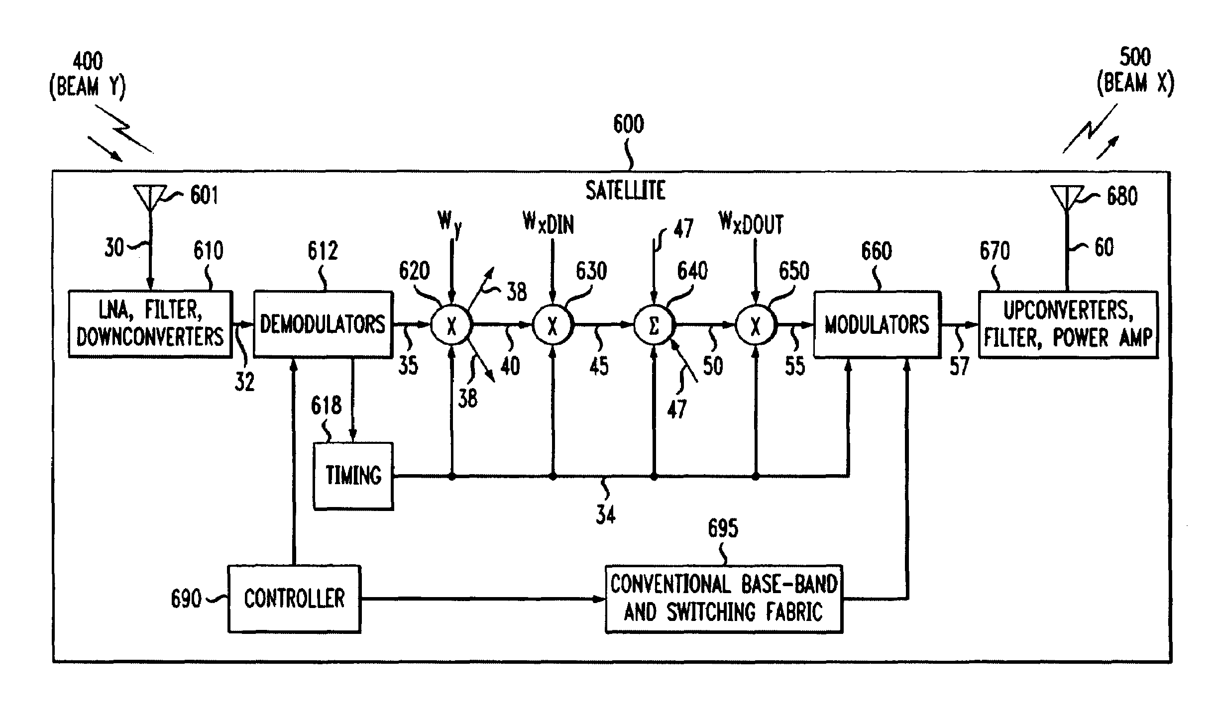
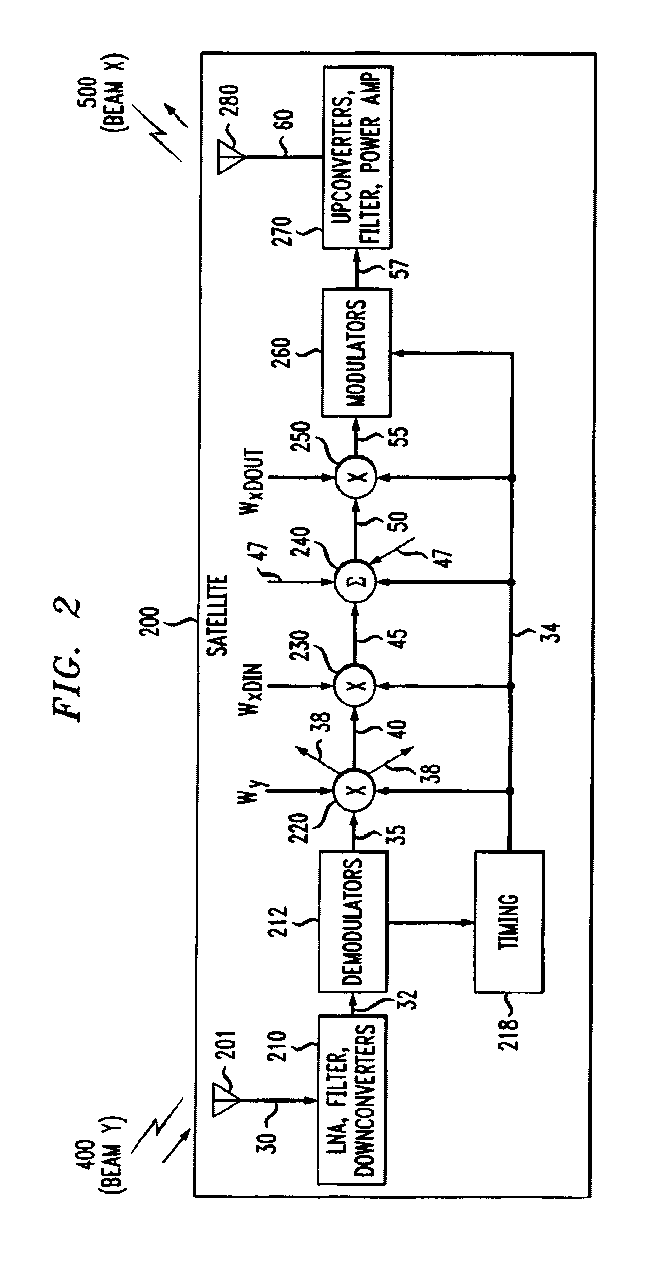
[0014]However, there remains a need for a seamless, flexible satellite communication network that can provide desired user services with high performance while still keeping switching equipment costs a minimum. The present invention introduces a distributed switching arrangement that utilizes matched filtering techniques to minimize the complexity of the switching fabric. This invention solves the current problem of performing robust, seamless communication without adding undue complexity and cost to the on-board communications equipment by switching user signals at the beam level rather than at the user level.
[0015]This invention separately provides a method and apparatus that reduces complexity and decreases signal bit-error rate for communication networks. By reducing the complexity of the satellite communication networks, the cost and maintenance of the satellite communication network is also reduced.
[0017]This invention separately calculates the on-board switching equipment volume to decrease bit-error rate by taking into account the number of origination and destination beams. The resulting decrease in bit-error rate improves user signal performance.
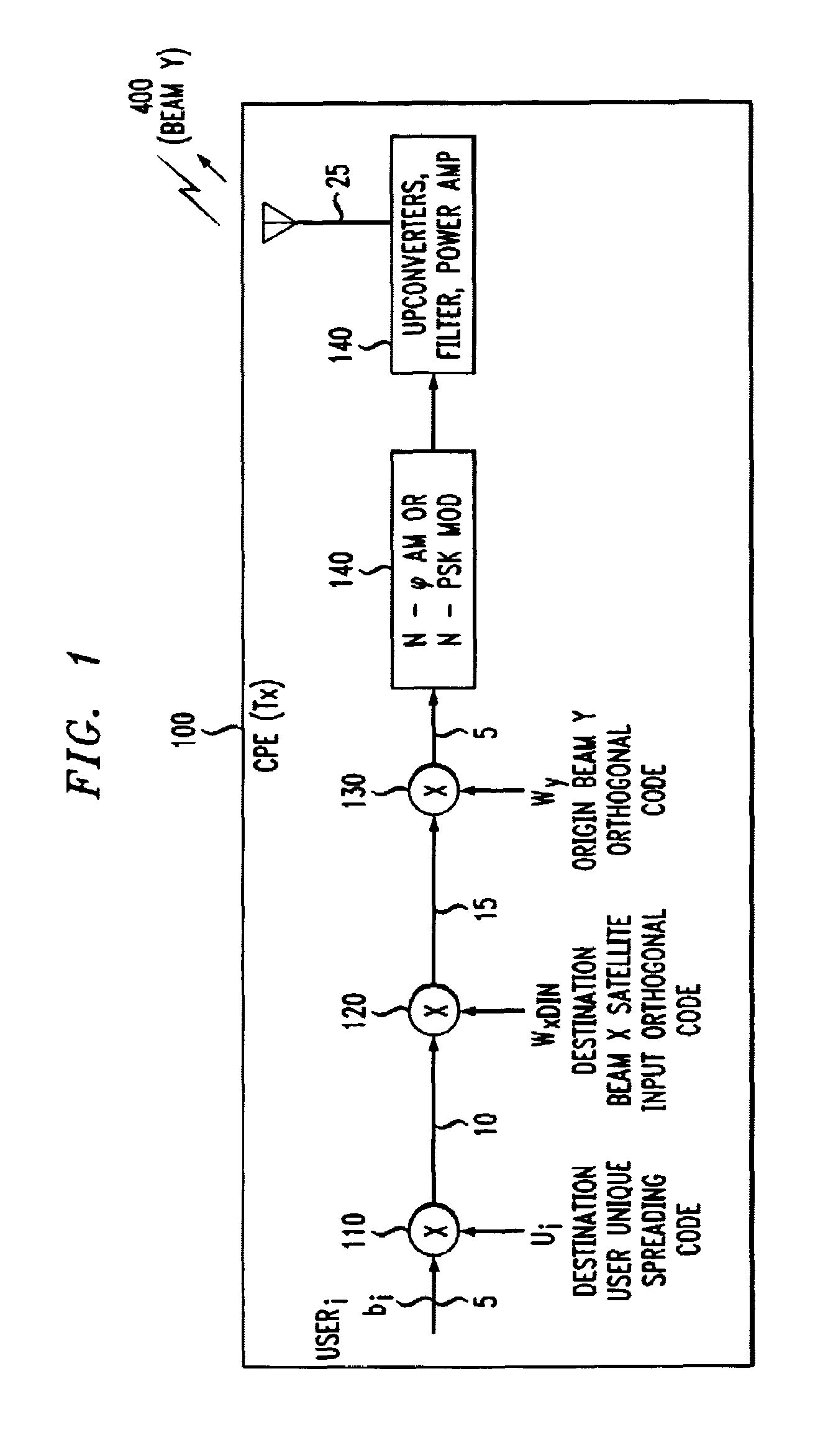
[0018]This invention separately uses common coding schemes at the originating and destination customer premises equipment sites to perform self-routing of user signals to the appropriate destination for more robust, flexible, and seamless performance.
[0020]This invention separately uses baseband self-routing to switch user signals on a per-beam basis instead of on a per-user basis in order to reduce the complexity of the on-board switching fabric.

Problems solved by technology

However, there remains a need for a seamless, flexible satellite communication network that can provide desired user services with high performance while still keeping switching equipment costs a minimum.

Method used


Image

  • Multiple access spread spectrum switching methodology
  • Multiple access spread spectrum switching methodology
  • Multiple access spread spectrum switching methodology

Examples


Embodiment Construction

[0026]When user signals are transmitted in a satellite environment in which several beams are available for origination beam transmission from the transmitter to the satellite and several beams are available for destination beam transmission from the satellite to the destination receiver, a switching function, i.e., routing incoming user signals from an origination beam to an appropriate destination beam, is necessary. Such a switching function, performed in a conventional way on-board a satellite, utilizes devices that consume significant amounts of power, may be heavy and bulky (relative to the overall weight and dimensions of a satellite) and are generally expensive. Hence, there exists a need to provide switching capability that is light-weight, less bulky, consumes a minimal amount of power and is inexpensive.

[0027]The invention achieves these and other objectives by minimizing the amount of switching necessarily performed on-board the satellite. In the exemplary embodiments, t...


PUM


Abstract

A low-cost, low-power, low-complexity, small, high-reliability, robust, seamless satellite communication network is described. The network performs encoding of a user signal at the customer premises to enable routing of the user signal to an appropriate destination beam at the satellite requiring low power user signal processing. Routing information is embedded at the periphery of the network CPE's rather than at the satellite. Embedding the routing information in this way greatly reduces on-board switching complexity and increases signal to interference ratio for the user.

Description

[0001]This non-provisional application claims the benefit of U.S. Provisional Application Ser. No. 60 / 110,624, filed Dec. 2, 1998, the subject matter of which is incorporated herein by reference.BACKGROUND OF THE INVENTION[0002]1. Field of Invention[0003]This invention relates to the switching of multiple access and / or multiplexed signals and more particularly to the switching of multiple access and / or multiplexed spread spectrum signals. More specifically, this invention relates to the switching of multiple access spread spectrum signals at a beam level, such as in a satellite system where an origination signal contains information from a plurality of users that is destined to a plurality of users which are located on separate destination beams.[0004]2. Description of Related Art[0005]Traditionally, satellite communication systems consist of a “bent-pipe” arrangement in which signals originating from a ground station have to be transmitted to a ground-based switching center where t...

Claims


Application Information

Patent Timeline
IPC IPC(8): H04B7/185H04B7/212H04B7/216
CPCH04B7/18532H04B7/216H04B7/18513Y02D30/70
Inventor RUDRAPATNA, ASHOK N.
Owner AMERICAN TELEPHONE & TELEGRAPH CO
Learn More