
Process for decoding signals and system and computer program product therefore

Active Publication Date: 2005-12-27
STMICROELECTRONICS SRL
View PDF11 Cites 20 Cited by
  • Summary
  • Abstract
  • Description
  • Claims
  • Application Information

AI Technical Summary

Benefits of technology

[0021]The solution according to the invention firstly simplifies the decoder structure, thereby overcoming the need for filter banks or error event tables. The invention also offers the possibility of correcting double error events in longer codewords. It is also possible to estimate correction reliability or, for example, detect multiple error events. Finally, the possibility of managing soft data permits the implementation of additional strategies directed at preventing correction errors.

Problems solved by technology

Creating an optimal detector is not always possible in encoding.
However they are intrinsically vulnerable with respect to correction errors and, particularly, to the possible propagation of such errors.

Method used


Image

  • Process for decoding signals and system and computer program product therefore
  • Process for decoding signals and system and computer program product therefore
  • Process for decoding signals and system and computer program product therefore

Examples


Embodiment Construction

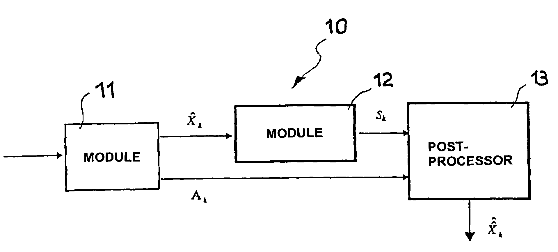
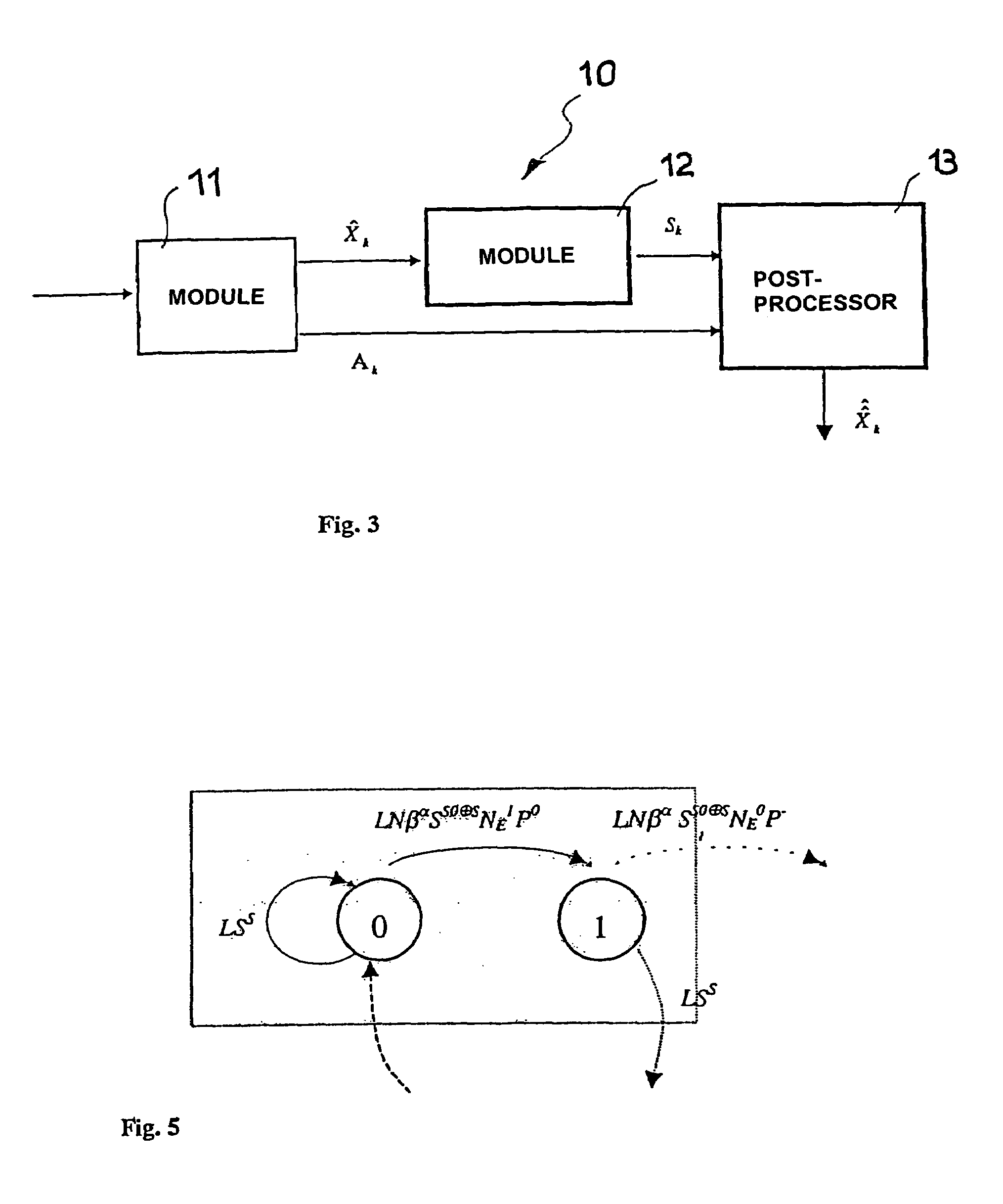
[0027]In FIG. 3, numeral 10 generally refers to apparatus intended to be used for decoding digital signals subjected to block coding and transferred on a channel. With reference to this, it is emphasized that for the purpose of this invention, the “channel” does not need to be a (tele)communications channel strictly speaking, but can also be, for example, a medium on which encoded data are stored for a given length of time.

[0028]Particularly, the apparatus according to this invention is based on the use of reliability values (“reliability”, in short) of a decoder matched to a partial response channel or to a generic code (for example, by means of a SOVA algorithm).

[0029]In the diagram of FIG. 3, X^k is the vector expressing the estimate of the “kth” encoded word. This vector is sent to a module 12 which computes the syndrome outputting a vector (n−k, 1), called Sk, containing the syndrome of the codeword (e.g. given by Xk*HT, where H is the parity matrix of the code).

[0030]Conversel...


PUM


Abstract

A system for decoding digital signals subjected to block coding includes a post-processor that corrects the codewords affected by error, identifying them with the most likely sequence that is a channel sequence and that satisfies a syndrome check. The post-processor is a finite-state machine described by a graph that represents the set of error events. The post-processor evolves in steps through subsequent transition matrices, deleting at each step the paths that accumulate an invalid number of error events or an excessive number of wrong bits, paths that accumulate a total reliability higher than a given threshold, paths with an invalid check on the received sequence, and paths that reveal an invalid syndrome after having reached a maximum number of events.

Description

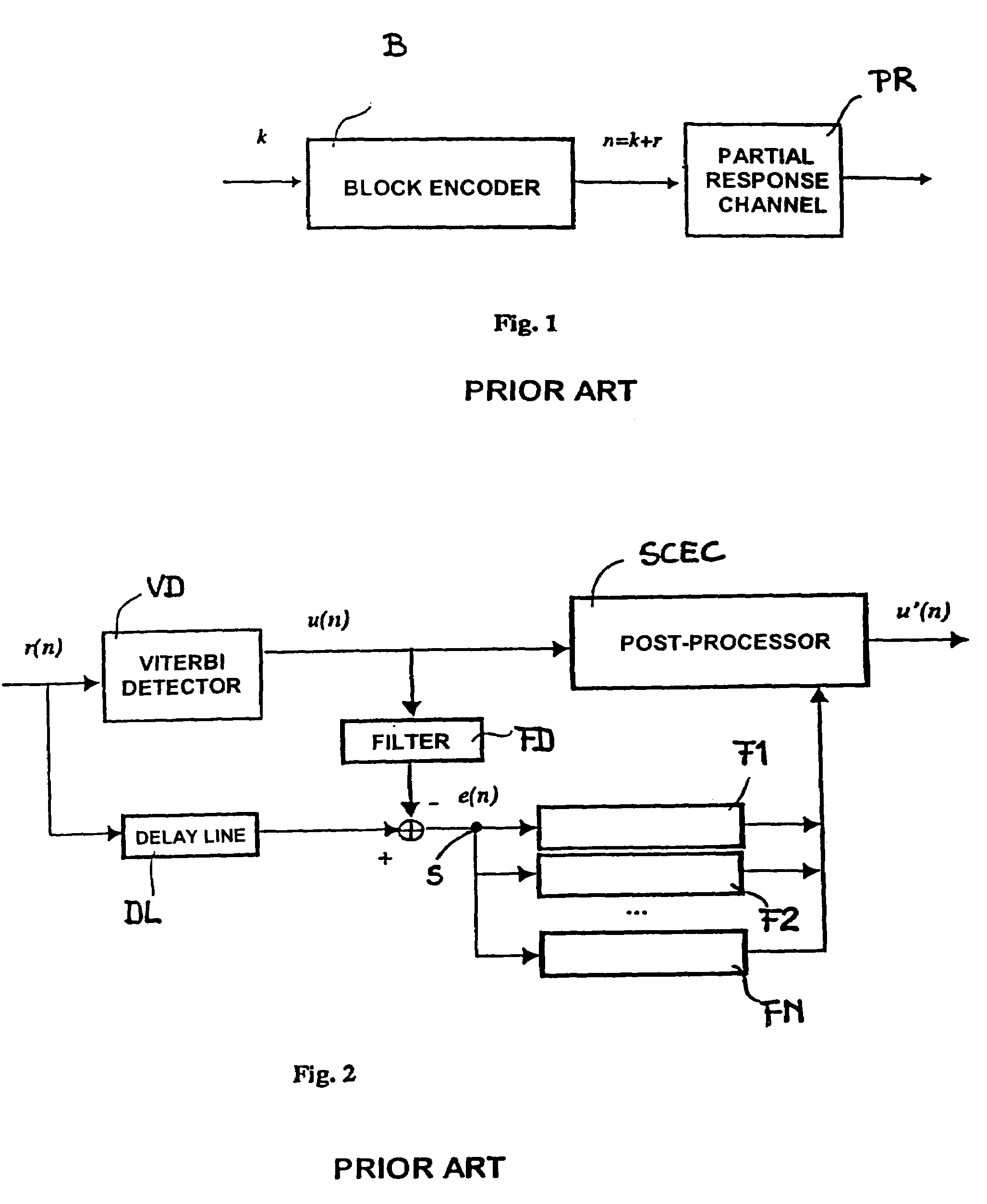
FIELD OF THE INVENTION[0001]The invention relates to techniques of decoding signals and specifically concerns techniques for decoding digital signals subjected to block coding. Particularly, the invention concerns a technique which is applied when decoding follows another decoding block pertaining to a channel or to another code, e.g. of the convolutional type.BACKGROUND OF THE INVENTION[0002]Solutions implementing a post-processor after channel detection are currently used in communication systems, also for possible use in signal storage.[0003]The diagram in FIG. 1 illustrates the typical concatenation between an encoder B which receives an input digital signal organised in blocks of length k and outputs a coded signal organised in blocks comprising n=k+r bits. Generally, an error correction code is a binary block code (n, k) based on an ad hoc parity check matrix H (or polynomial p(D)).[0004]A typical partial response channel PR is shown cascaded to block encoder B.[0005]Creating ...

Claims


Application Information

Patent Timeline
IPC IPC(8): H03M13/41H03M13/45
CPCH03M13/41H03M13/45
Inventor REGGIANI, LUCABETTI, GIORGIOBRENNA, FILIPPODATI, ANGELOGIOVENZANA, DAVIDEROSSI, AUGUSTO
Owner STMICROELECTRONICS SRL
Learn More