Apparatus and method for producing a pressurized vapor stream

a technology of apparatus and vapor stream, which is applied in the direction of fluid coupling, container discharging method, steam generation using hot heat carriers, etc., can solve the problems of difficult, if not impossible, to accurately adjust the transmission retarder, and the amount of heat generated in the hydraulic circuit used to power the cryopump, etc., to achieve less complex and expensive devices, easy scalable, and precise control

Active Publication Date: 2006-01-03
PRAXAIR TECH INC +1
View PDF6 Cites 27 Cited by
  • Summary
  • Abstract
  • Description
  • Claims
  • Application Information

AI Technical Summary

Benefits of technology

[0015]There are many advantages of the present invention as set forth above over the prior art. The foremost advantage is that the independent control of backpressure in both the first and second hydraulic fluid flow paths by adjustable back pressure valves controls that amount of heat generated more precisely than prior art devices so that the pumping output and the required heat transfer duty can be closely matched on a broad range of potential operation. It goes without saying that backpressure valves are far less complex and expensive devices than dynamometers and provide more precise control than transmission retarders. Furthermore, as will become apparent, the present invention is easily scalable by simply adding hydraulic power generation systems and sets of first and second flow paths.

Problems solved by technology

The prior art as disclosed in the above referenced patents presents rather complex systems that have a rather limited range of control.
While U.S. Pat. No. 4,438,729 employs both a adjustable back pressure valve and a transmission retarder to provide two points of adjustment and therefore, the potential of greater heat control, it is difficult, if not impossible, to accurately adjust a transmission retarder and therefore, the amount of heat generated in the hydraulic circuit used in powering the cryopump.
Furthermore, the use of such equipment as dynamometers and transmission retarders present unwanted expense and complexity.
A further deficiency in pressurization systems of the prior art is that such systems it is not easily scalable to provide apparatus that is efficient for a particular operation.

Method used


Image

  • Apparatus and method for producing a pressurized vapor stream
  • Apparatus and method for producing a pressurized vapor stream

Examples


Embodiment Construction

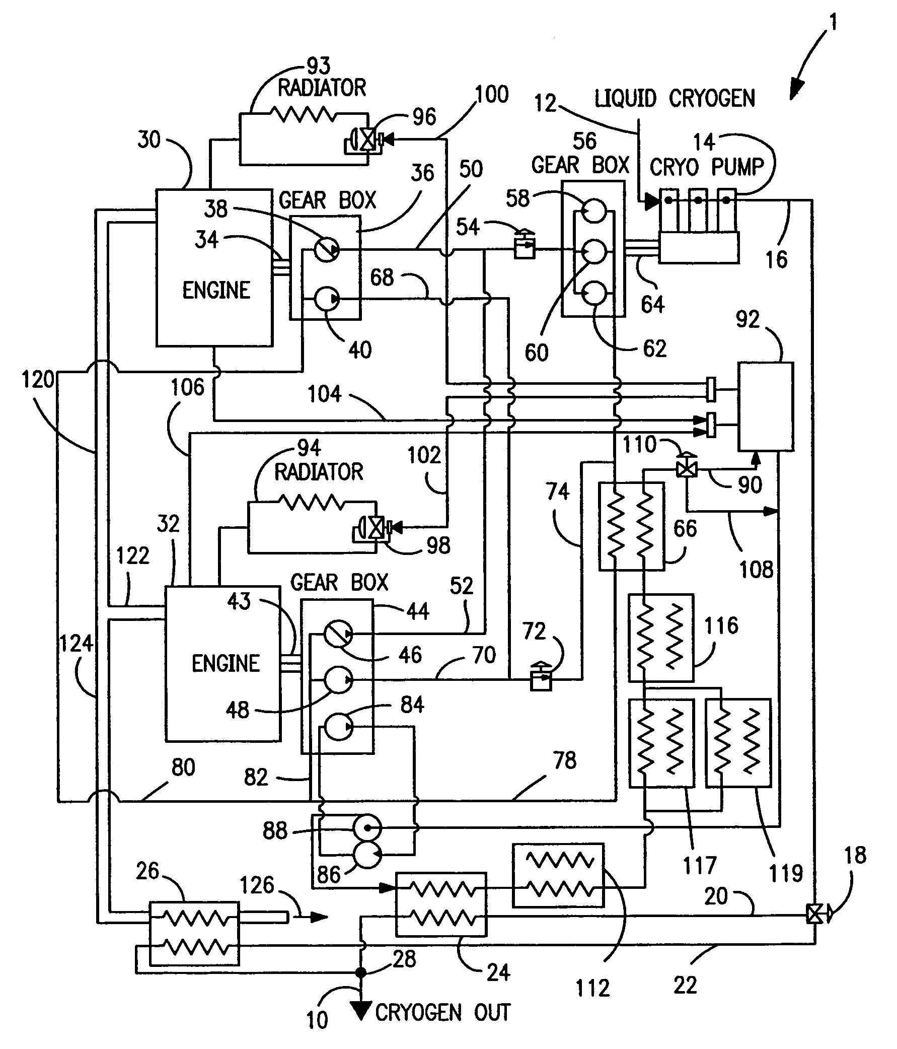
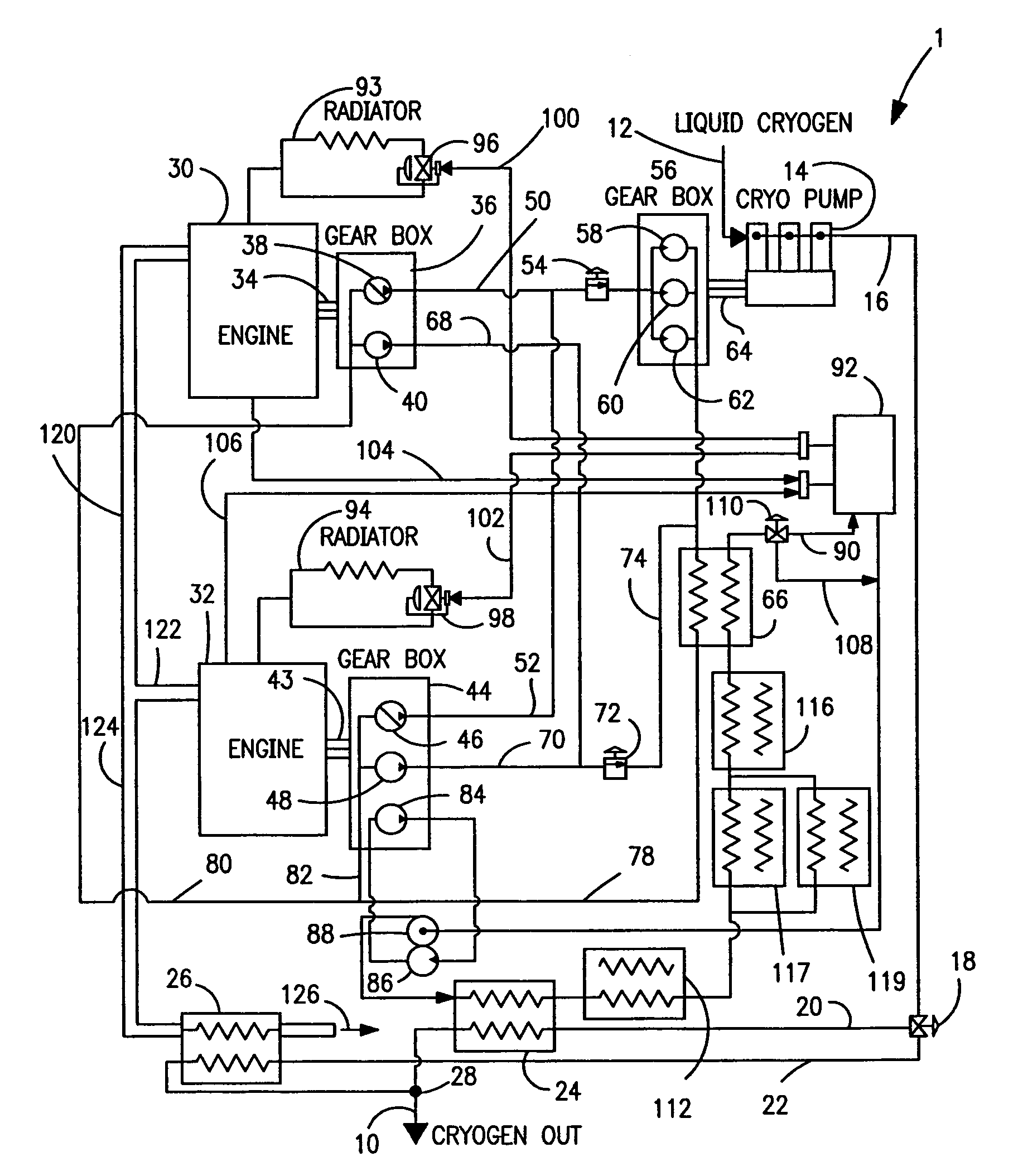
[0033]With reference to the sole FIGURE, an apparatus 1 in accordance with the present invention as illustrated for producing a pressurized vapor stream 10 which, for exemplary purposes can be made up of nitrogen.

[0034]A cryogenic stream 12 is pumped by a cryopump 14 to produce a pressurized liquid stream that flows through a conduit 16 from the cryopump 14. Conduit 16 is optionally connected to a diverter valve 18 that is connected to conduits 20 and 22 that provide first and second pressurized liquid flow paths, respectively. The first of the pressurized liquid flow paths provided by conduit 20 is connected to a vaporizer 24 which functions to vaporize a pressurized liquid stream flowing within conduit 20. Vaporizer 24 can be a water bath vaporizer of shell and tube design. The pressurized liquid stream flowing into the second of the pressurized liquid flow paths provided by conduit 22 passes to an exhaust gas vaporizer 26 and then to junction 28 connecting conduits 20 and 22. Exh...


PUM


Abstract

A cryogenic stream is pumped by a cryopump and then vaporized in a vaporizer to produce the pressurized vapor stream. The cryopump is driven by a transmission that is in turn driven by a hydraulic fluid. The hydraulic fluid flows within a hydraulic fluid circuit having first and second hydraulic fluid flow paths. The first of the flow paths is used to drive the hydraulic transmission. The second of the flow paths is dedicated to raising heat. Hydraulic fluid is circulated within the flow path by hydraulic fluid pumps and the amount of heat generated is controlled by adjustable back pressure valves. The adjustable back pressure valves in both fluid flow paths can be adjusted to control the degree to which heat is added to the vaporizer and therefore the pressurized vapor stream. The hydraulic fluid pumps can be driven by diesel engines. Heat may also be recovered from the diesel engines and gear oil used in pumps and the cryopump to also help vaporize the pressurized liquid stream. The aforesaid system of first and second pumps driven by an engine and first and second flow paths can be replicated to allow for expansion of pumping capacity.

Description

FIELD OF THE INVENTION[0001]The present invention relates to an apparatus and method for producing a pressurized vapor stream in which a cryogenic liquid stream is pumped by a cryopump to produce a pressurized liquid stream and then subsequently vaporized to produce the pressurized vapor stream. More particularly, the present invention relates to such an apparatus and method in which heat for the vaporization of the pressurized liquid stream is obtained from a hydraulic fluid circuit having a back pressured flow path to drive the cryopump and to generate part of the heat and another back pressured flow path to generate a further part of the heat required for vaporization.BACKGROUND OF THE INVENTION[0002]There are a variety of industrial processes that require a pressurized vapor. Pressurized vapor is often produced by pumping a cryogenic liquid and then vaporizing the pumped liquid. Typical cryogenic liquids are those obtained from the fractionation of air into its separate componen...

Claims


Application Information

Patent Timeline
Patent Type & Authority Patents(United States)
IPC IPC(8): F04B9/08F04B23/14F17C13/02
CPCF22B1/18F17C2227/0135F17C2227/0393
Inventor MALTBIE, BRIAN NORMANWHITE, NORMAN HENRY
Owner PRAXAIR TECH INC
Why Eureka
Try Eureka