Recording/reproducing head and recording/reproducing apparatus incorporating the same

a recording/recording head and recording/recording head technology, applied in the manufacture of the head surface, recording on magnetic tapes, instruments, etc., can solve the problems of reducing the output of reproduced, short circuits, and large aspect ratios, and achieves easy rotation, easy rotation, and easy rotation

Inactive Publication Date: 2006-01-03
PANASONIC CORP
View PDF21 Cites 33 Cited by
  • Summary
  • Abstract
  • Description
  • Claims
  • Application Information

AI Technical Summary

Benefits of technology

[0016]In one embodiment of this invention, the first magnetoresistance device includes a first insulating layer provided on the magnetic head core; and a first pinned layer provided on a side opposite to the magnetic head core of the first insulating layer, in which a magnetization direction is not easily rotated in the first pinned layer. The magnetic head core includes a first soft magnetic layer provided at a position corresponding to the first insulating layer; and the first soft magnetic layer functions as a first free layer of the first magnetoresistance device, in which a magnetization direction is easily rotated in the first free layer.
[0017]In one embodiment of this invention, the second magnetoresistance device includes a second insulating layer provided on the magnetic head core; and a second pinned layer provided on a side opposite to the magnetic head core of the second insulating layer, in which a magnetization direction is not easily rotated in the second pinned layer. The magnetic head core includes a second soft magnetic layer provided at a position corresponding to the second insulating layer; and the second soft magnetic layer functions as a second free layer of the second magnetoresistance device, in which a magnetization direction is easily rotated in the second free layer.
[0040]According to a third aspect of the present invention, a magnetic head for reproducing a signal recorded on a recording medium, includes a substrate; a magnetic head core provided on the substrate, having a magnetic gap; and a first magnetoresistance device provided on the magnetic head core. The first magnetoresistance device includes a first insulating layer provided on the magnetic head core; and a first pinned layer provided on a side opposite to the magnetic head core of the first insulating layer, in which a magnetization direction is not easily rotated in the first pinned layer. The magnetic head core includes a first soft magnetic layer provided at a position corresponding to the first insulating layer; and the first soft magnetic layer functions as a first free layer of the first magnetoresistance device, in which a magnetization direction is easily rotated in the first free layer.
[0041]In one embodiment of this invention, the magnetic head further includes a second magnetoresistance device provided on the magnetic head core. The second magnetoresistance device includes a second insulating layer provided on the magnetic head core; and a second pinned layer provided on a side opposite to the magnetic head core of the second insulating layer, in which a magnetization direction is not easily rotated in the second pinned layer. The magnetic head core includes a second soft magnetic layer provided at a position corresponding to the second insulating layer; and the second soft magnetic layer functions as a second free layer of the second magnetoresistance device, in which a magnetization direction is easily rotated in the second free layer.
[0070]According to a seventh aspect of the present invention, a recording / reproducing apparatus includes a first magnetic head for recording a signal onto a recording medium; and a second magnetic head for reproducing the signal recorded on the recording medium. The first magnetic head includes a first substrate; a first magnetic head core provided on the first substrate, having a first magnetic gap: and a coil provided in such a manner that at least a portion of the magnetic head core is surrounded by the coil. The first magnetic head core is provided in such a manner that a thickness direction of the first magnetic head core around the first magnetic gap is substantially the same as a track width direction of the recording medium. The second magnetic head includes a second substrate; a second magnetic head core provided on the second substrate, having a second magnetic gap; and a first magnetoresistance device provided on the second magnetic head core. The first magnetoresistance device includes an insulating layer provided on the second magnetic head core; and a pinned layer provided on a side opposite to the second magnetic head core of the insulating layer, in which a magnetization direction is not easily rotated in the pinned layer. The second magnetic head core includes a soft magnetic layer provided at a position corresponding to the second insulating layer; and the soft magnetic layer functions as a free layer of the first magnetoresistance device, in which a magnetization direction is easily rotated in the free layer.
[0073]Thus, the invention described herein makes possible the advantages of providing hyper-density recording of about 100 Gb / inch2, and a recording / reproducing apparatus incorporating a magnetic head driving portion having a high-accuracy tracking performance in such hyper-density recording.

Problems solved by technology

When a tunnel type GMR (TMR) device is used instead of the GMR device 1014, a short circuit is likely to occur.
Such a gap, however, leads to a reduction in reproduced output.
This leads to an extraordinarily large aspect ratio and thus difficulty in processing.
To this end, various methods have been proposed, but there still remains challenges insofar as practical use.
There is a problem in that recording and reproducing are performed by the separate heads.
There is a problem in that the higher the density of recording, the greater the technical difficulty.
In this case, there is also a significant problem with the processing of the small-width track in the HDD recording head as described above.
For that reason, it is impossible to provide heads on the upper and lower sides of a disk and utilize both sides of the disk as recording surfaces.
In terms of space-saving, such a structure is disadvantageous to the recording / reproducing apparatus.
In addition to the above-described problems, the higher the density of recording, the greater the difficulty in servo tracking when only one magnetic head driving section is provided in a conventional recording / reproducing apparatus.

Method used


Image

  • Recording/reproducing head and recording/reproducing apparatus incorporating the same
  • Recording/reproducing head and recording/reproducing apparatus incorporating the same
  • Recording/reproducing head and recording/reproducing apparatus incorporating the same

Examples


example 1

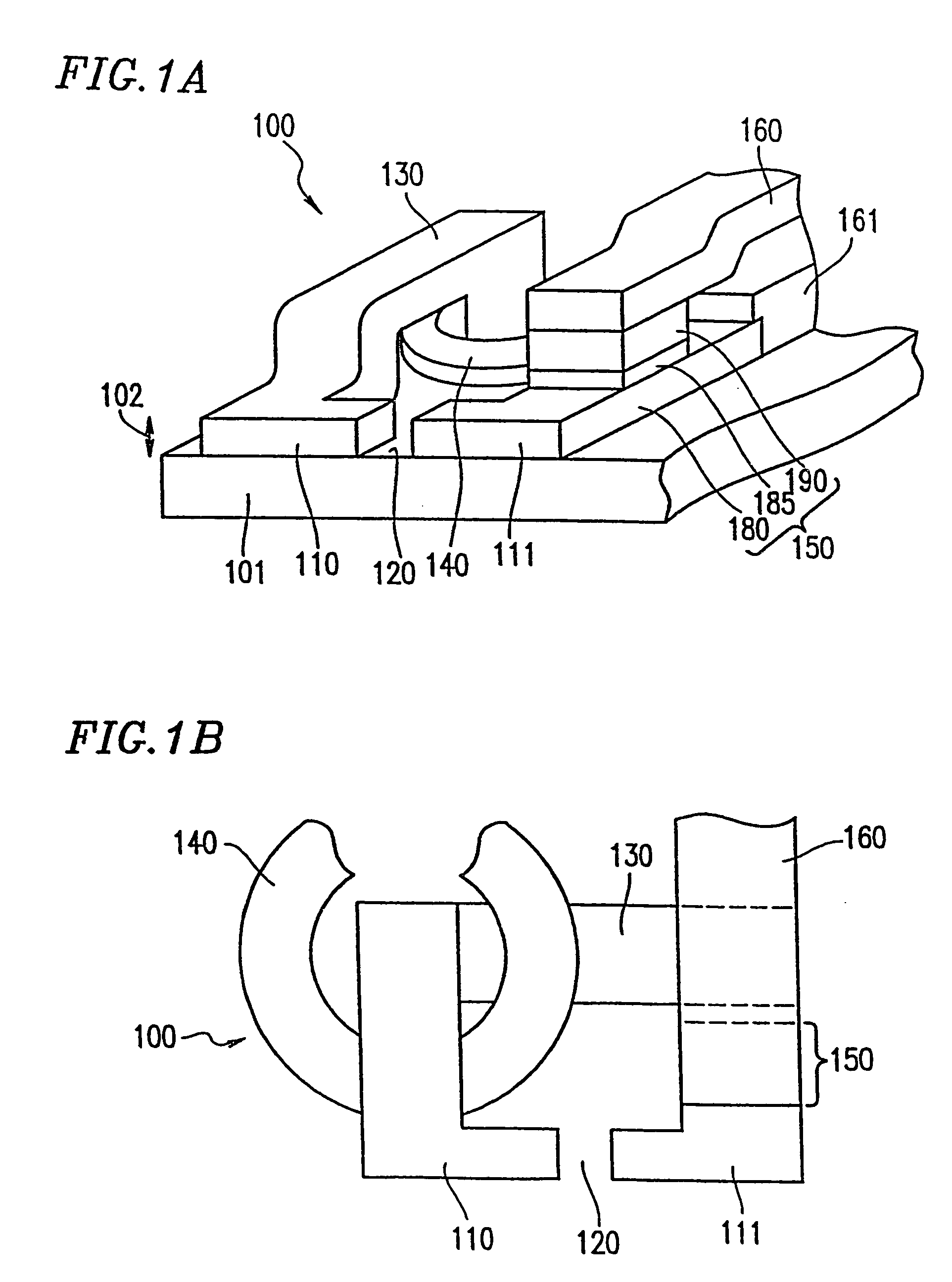
[0092]FIGS. 1A and 1B show a magnetic head 100 according to Example 1 of the present invention. FIG. 1A is a perspective view of the magnetic head 100. FIG. 1B is a plan view of the magnetic head 100. The magnetic head 100 includes a magnetic head core 130, a coil portion 140, and a magnetoresistance device 150 which are provided on a substrate 101. The magnetic head core 130 includes soft magnetic films 110 and 111, and a magnetic gap 120. The coil portion 140 generates a magnetic field in the magnetic head core 130 to write a signal onto a recording medium 116 (FIG. 5). The magnetoresistance device 150 reads a magnetic flux from the recording medium 116.

[0093]When recording onto the recording medium 116, a magnetic field is generated in the magnetic head core 130 by the coil portion 140 in accordance with a signal to be recorded. The generated magnetic field is applied to a magnetic layer 117 (FIG. 5) of the recording medium 116.

[0094]When reproducing from the recording medium 116...

example 2

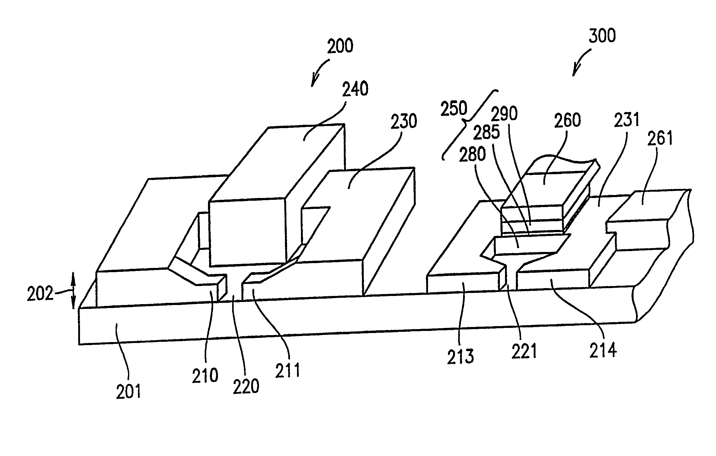
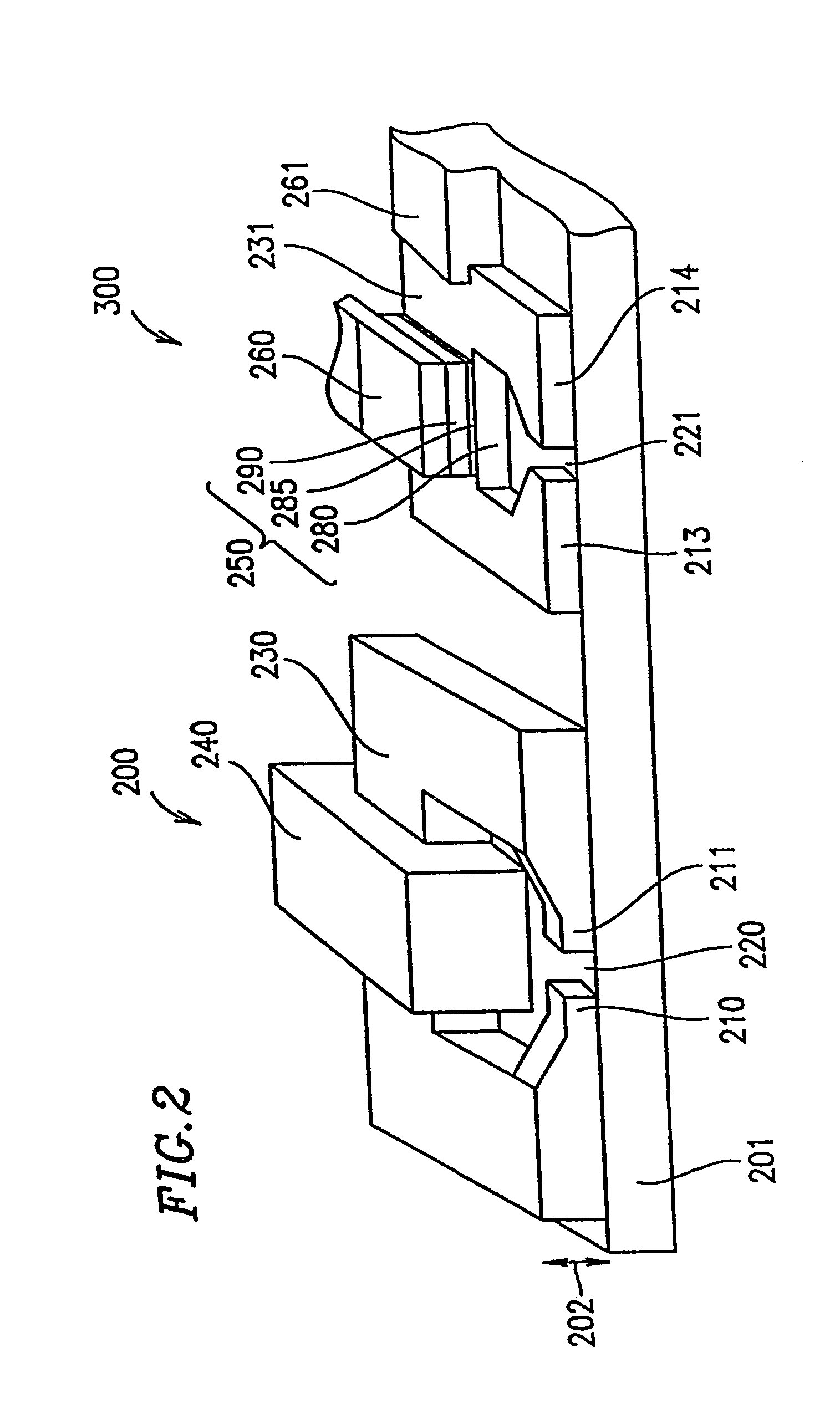
[0100]FIG. 2 is a perspective view of magnetic heads 200 and 300 according to Example 2 of the present invention.

[0101]In the above-described magnetic head 100 of Example 1, the single magnetic head is used in both recording and reproducing. On the other hand, in Example 2, the magnetic head 200 having a coil portion 240 which is used for recording and the magnetic head 300 having a magnetoresistance device 250 which is used for reproducing are separately provided on a substrate 201.

[0102]The magnetic head 200 includes a magnetic head core 230 and the coil portion 240. The magnetic head core 230 is provided on the substrate 201 and has a magnetic gap 220. The coil portion 240 generates a magnetic flux in the magnetic head core 230 for writing a signal onto the recording medium 116 (FIG. 5A).

[0103]The magnetic head 300 includes a magnetic head core 231 and the magnetoresistance device 250. The magnetic head core 231 is provided on the substrate 201 and has a magnetic gap 221. The mag...

example 3

[0110]FIG. 3 is a perspective view of a magnetic head 400 according to Example 3 of the present invention. The magnetic head 400 includes a magnetic head core 331 and a magnetoresistance device 350 which are provided on a substrate 201. The magnetic head core 331 includes soft magnetic films 313 and 314. The magnetoresistance device 350 includes a free layer 380, a pinned layer 290, and an insulating layer 285. The insulating layer 285 isolates the free layer 380 from the pinned layer 290. The other structure of the magnetic head 400 is the same as the corresponding structure of the magnetic head 300 of Example 2.

[0111]In Example 3, the thickness of a region serving as the free layer 380 of the magnetoresistance device 350 of the magnetic head core 331 and a surrounding region thereof is smaller than the thickness of the other region of the magnetic head core 331. For that reason, a magnetic flux flowing through the magnetic head core 331 is converged into the free layer 380 so that...


PUM

PropertyMeasurementUnit
widthaaaaaaaaaa
lengthaaaaaaaaaa
track widthaaaaaaaaaa

Abstract

A magnetic head for reproducing a signal recorded on a recording medium, includes a substrate, a magnetic head core provided on the substrate, having a magnetic gap, and a magnetoresistance device provided on the magnetic head core. The magnetic head core is provided in such a manner that a thickness direction of the magnetic head core around the magnetic gap is substantially the same as a track width direction of the recording medium.

Description

[0001]This is a division of application Ser. No. 10 / 293,420, filed Nov. 12, 2002 now U.S. Pat. No. 6,650,598, which is a division of U.S. application Ser. No. 09 / 603,072, filed Jun. 26, 2000, now U.S. Pat. No. 6,504,796.BACKGROUND OF THE INVENTION[0002]1. Field of the Invention[0003]The present invention relates to a recording / reproducing head and a recording / reproducing apparatus incorporating the recording / reproducing head. More particularly, the present invention relates to a recording / reproducing head, a recording / reproducing apparatus, and a fabrication method thereof which are capable of higher-density recording than conventional hard disks and magneto-optical disk apparatuses.[0004]2. Description of the Related Art[0005]A hard disk drive (HDD) 1000 represented in FIG. 11 or a magneto-optical disk (MO) apparatus 2000 represented in FIG. 12 can record information signal in high density. These apparatuses include a magnetic head 1019 and a magneto-optical head 2020, respectively...

Claims


Application Information

Patent Timeline
Patent Type & Authority Patents(United States)
IPC IPC(8): G11B11/00G11B5/65G11B5/00G11B5/008G11B5/012G11B5/23G11B5/31G11B5/39G11B5/48G11B5/58G11B5/64G11B5/66G11B11/10G11B11/105G11B13/04
CPCB82Y10/00B82Y25/00G11B5/00G11B5/39G11B5/48G11B5/58G11B13/04G11B5/3951G11B5/00813G11B5/012G11B2005/3996G11B2005/0002G11B2005/0005G11B2005/0021G11B5/23
Inventor SAKAKIMA, HIROSHIBIRUKAWA, MASAHIROYOKOYAMA, KAZUOHIRAMOTO, MASAYOSHI
Owner PANASONIC CORP
Why Eureka
Try Eureka