
Systems and methods for manufacturing a product in a pull and push manufacturing system and associated methods and computer program products for modeling the same

Inactive Publication Date: 2006-01-03
THE BOEING CO
View PDF15 Cites 11 Cited by
  • Summary
  • Abstract
  • Description
  • Claims
  • Application Information

AI Technical Summary

Benefits of technology

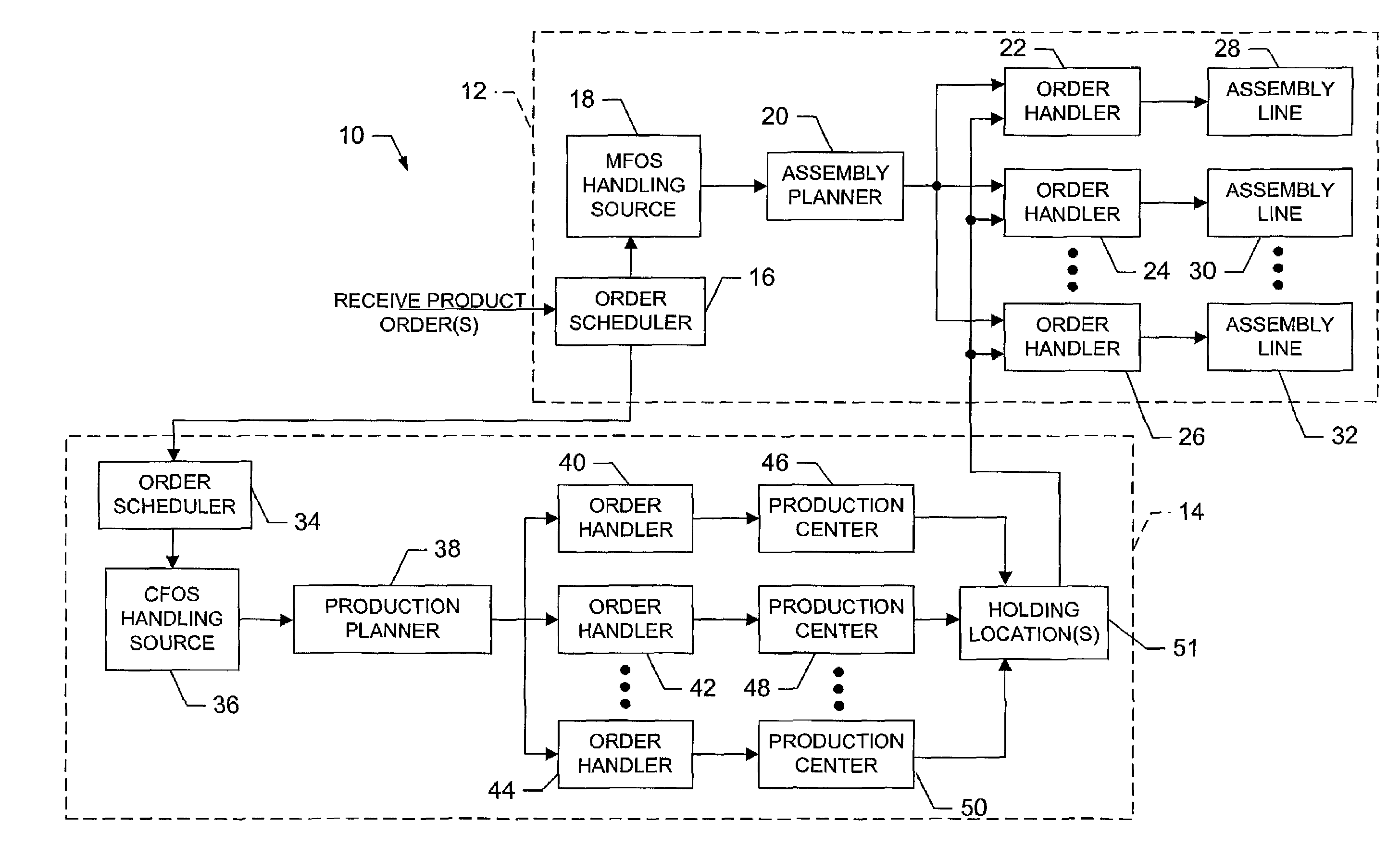
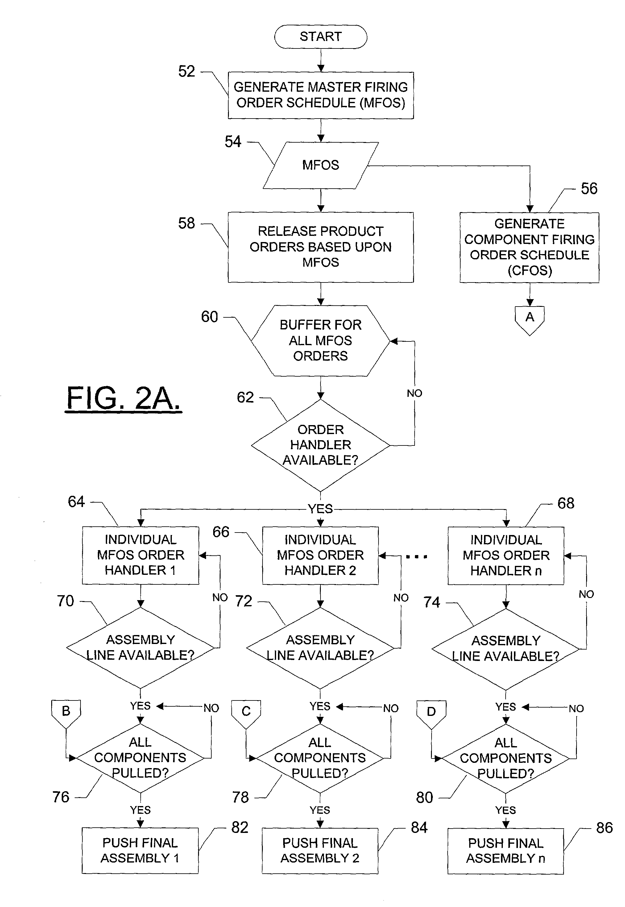
[0007]In light of the foregoing background, the present invention provides an improved system and method of manufacturing a product in a pull and push manufacturing system, and an associated method and computer program product for modeling the same. In this regard, the product comprises at least one model that includes at least one component. According to embodiments of the present invention, a production schedule for producing the components is based upon the different manufacturing times of the components, as well as an order schedule for the models of the product. As such, the present invention accounts for the fact that one or more components from subsequent orders may require longer production times than an original order. Also, according to embodiments of the present invention, efficiency of the system is improved by the fact that the efficiency of producing the components is not solely based upon producing as many of a given component as possible at the same time. In this regard, according to the present invention, the efficiency of producing components is based upon producing each component as quickly as possible as an order for a model of the product including the respective component is received by the system, or released to assembly.
[0011]The processing element can measure an efficiency of the system based upon a number of subsequent components buffered and / or a number of subsequent orders buffered. In this regard, the processing element can adjust the set assembly time for at least one of the models of the product, the set manufacturing time for at least one of the components of the models, the set number of production centers, and / or the set number of assembly lines based upon the measured efficiency. For example, the processing element can model the system by setting the number of production centers and the manufacturing time associated with each component before simulating operation of the system. Then, the processing element can measure the efficiency by comparing the number of subsequent orders buffered to a threshold such that, when the number of subsequent components buffered is greater than the threshold, the processing element can increase the number of production centers and / or decrease the manufacturing times of the respective components.
[0012]Also for example, the processing element can model the system by setting the number of assembly lines and the assembly time associated with each model of the product. The processing element can then measure the efficiency by comparing the number of subsequent orders buffered to a threshold such that, when the number of subsequent orders buffered is greater than the threshold, the processing element can increase the number of assembly lines and / or decrease the assembly times of the respective models ordered.
[0013]Additionally, or alternatively, the processing element can be capable of further modeling the system by measuring the efficiency of the system based upon an amount of time subsequent components are buffered and / or an amount of time subsequent orders are buffered. In such an embodiment, the processing element can adjust the set assembly time for at least one of the models of the product, the set manufacturing time for at least one of the components of the models, the set number of production centers, and / or the set number of assembly lines based upon the measured efficiency. For example, the processing element can set the number of production centers and the manufacturing time associated with each component before simulating operation of the system. Then, the processing element is capable of measuring an efficiency by comparing an amount of time subsequent orders are buffered to a threshold such that, when subsequent components are buffered for longer than the threshold, the processing element can increase the number of production centers and / or decrease the manufacturing times of the respective components.
[0014]In another example, the processing element can set the number of assembly lines and the assembly time associated with each model of the product. In this regard, the processing element is capable of measuring an efficiency by comparing an amount of time subsequent orders are buffered to a threshold. And when subsequent orders are buffered for longer than the threshold, the processing element can increase the number of assembly lines, decrease the assembly times of the respective models ordered, increase the number of production centers and / or decrease the manufacturing times of the respective components.

Problems solved by technology

In reality, however, many factors within the manufacturing that disrupt the manufacture of the components and / or the assembly of the products and, therefore, create inefficiencies in the overall manufacturing systems.
Because of the factors that create inefficiencies in large scale manufacturing systems, many manufacturers research and develop contemplated manufacturing systems prior to implementing the systems.
Whereas many manufacturing systems and techniques for modeling manufacturing systems are adequate, such systems and techniques also have drawbacks, many of which stem from a lack of interaction between the assembly of products and the production of the components that are thereafter assembled into the products.
As such, inefficiencies result in scheduling the production of components from the original order prior to scheduling the production of components from subsequent orders, where the components from the subsequent orders require longer production times.
Further, on a product level, as many conventional modeling techniques base the efficiency of assembling products on assembling the products at a particular location, or assembly facility, designated for the assembly of that product, such modeling techniques inefficiently utilize the assembly facilities.

Method used


Image

  • Systems and methods for manufacturing a product in a pull and push manufacturing system and associated methods and computer program products for modeling the same
  • Systems and methods for manufacturing a product in a pull and push manufacturing system and associated methods and computer program products for modeling the same
  • Systems and methods for manufacturing a product in a pull and push manufacturing system and associated methods and computer program products for modeling the same

Examples


Embodiment Construction

[0018]The present invention now will be described more fully hereinafter with reference to the accompanying drawings, in which preferred embodiments of the invention are shown. This invention may, however, be embodied in many different forms and should not be construed as limited to the embodiments set forth herein; rather, these embodiments are provided so that this disclosure will be thorough and complete, and will fully convey the scope of the invention to those skilled in the art. Like numbers refer to like elements throughout.

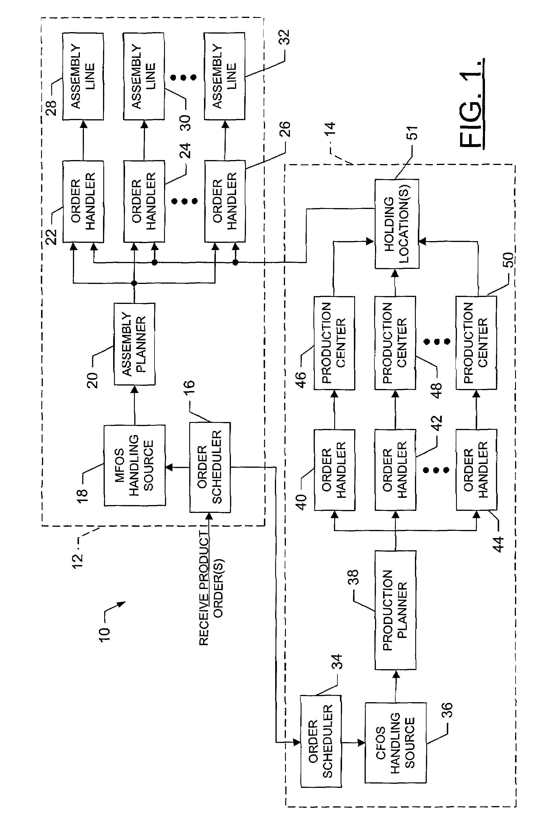
[0019]Referring to FIG. 1, a system 10 for manufacturing a product that comprises at least one model including at least one component is provided. The system includes an assemble-to-order (ATO) portion 12 and a make-to-order (MTO) portion 14. According to the system, the ATO portion receives orders for the product, such as into an order scheduler 16. The order scheduler can comprise any of a number of different entities including, for example, a sales depa...


PUM


Abstract

A system of manufacturing a product in a pull and push manufacturing system is provided, where the product comprises at least one model and each model includes at least one component. The system includes an order scheduler, a component scheduler, a make-to-order (MTO) portion and an assemble to order (ATO) portion. The order scheduler is capable of receiving order(s) for model(s) of the product, and the component scheduler is capable of generating a component firing order schedule (CFOS) for the components corresponding to the models ordered. The MTO portion can release each component and thereafter produce the components. And the ATO portion can release each order and thereafter assemble the orders released from the produced components at a number of assembly lines. Advantageously, a number of system parameters can be determined based upon modeling the manufacturing system.

Description

FIELD OF THE INVENTION[0001]The present invention relates to systems and methods of manufacturing a product and, more particularly, to systems and methods for manufacturing a product in a manufacturing system integrating pull, push, make-to-order and assemble-to-order processes.BACKGROUND OF THE INVENTION[0002]In many industries that produce products on a large scale, manufacturing systems include pull and push processes, typically within individual make-to-order and assemble-to-order systems. Typically, within large scale manufacturing systems, orders for products are pushed to an assemble-to-order system, which assembles the products from the components that make up the products. Prior to assembling the product, however, the components must be manufactured, such as in a make-to-order system, either by the manufacturer of the product and / or one or more third party suppliers of various components of the product. In an ideal setting, then, the components of the products are manufactu...

Claims


Application Information

Patent Timeline
IPC IPC(8): G06F19/00G06Q10/06
CPCG06Q10/06
Inventor LU, ROBERTO F.
Owner THE BOEING CO
Learn More