Electronics assembly systems customer benefit modeling tools and methods

a technology of customer benefit and assembly system, applied in the field of electrical assembly system, can solve the problems of not being able to adequately take into account the interaction of various factors, not being able to predict the actual impact, and not being able to configure adequately to show the effect of various factors

Inactive Publication Date: 2006-01-03
SIEMENS ELECTRONICS ASSEMBLY SYST LLC +1
View PDF10 Cites 43 Cited by
  • Summary
  • Abstract
  • Description
  • Claims
  • Application Information

AI Technical Summary

Benefits of technology

[0008]The present invention provides methods and tools for modeling a configuration for, among other things, an electronics assembly system and generating performance measures associated with a given configuration based upon a simulation of the behavior of the system. In particular, the methods and tools make it possible for electronics assembly equipment salespersons or consultants to generate a simulation model for purposes of a sales pitch or a consulting project on the order of magnitude of about a half and hour, or even less, to conduct model-based prediction of system performance under various configuration assumptions, and to generate for an actual or prospective customer one or more expected cost of ownership values for particular configuration assumptions.
[0009]The customer benefit modeling tool of the present invention enables trained consultants to accurately model current and future customer assembly systems at the line, multi-line, shop floor and factory levels. It also enables the performance of customer systems to be expressed in a range of key metrics that include, for example, throughput, cost performance, yield, OEE and COO. The customer benefit tool according to the present invention can be used to accurately represent production reality because, in one embodiment, it can handle distributed inputs and events by using a dynamic model based on discrete event simulation. This modeling approach enables separate analysis of system design issues (e.g. equipment configuration, wip buffer sizing) and operations issues (e.g. staffing, material availability).
[0010]The customer benefit modeling tool can also provide customer / project specific target benchmarking under defined, ideal operating conditions (e.g. no break downs, no run outs). That is, the performance that one would expect under short duration “acceptance testing.” The tool may also be configured to enable target production metrics to be established based on realistic conditions. It can also be configured to model the impact of changing operations related variables.

Problems solved by technology

While spreadsheets are easy to use, and may provide results based on static modeling, they do not adequately take into account how various factors interact with each other.
For instance, a spreadsheet can be configured to show that certain pieces of equipment in an assembly line may have a downtime of 25%, but it cannot be configured adequately to show that at various times, all of these pieces of equipment might be down at the same time, much less predict the actual impact such an event might have on line performance.
One drawback of using existing discrete event simulation products is the amount of time and skill it takes to set up a discrete event simulation of an actual or proposed system.
This long turn-around time is not helpful for a salesperson pitching equipment, or consultants trying to demonstrate their ability to increase a line's efficiency.
Moreover, the level of skill required to build a simulation often exceeds that possessed by a typical salesperson.

Method used


Image

  • Electronics assembly systems customer benefit modeling tools and methods
  • Electronics assembly systems customer benefit modeling tools and methods
  • Electronics assembly systems customer benefit modeling tools and methods

Examples


Embodiment Construction

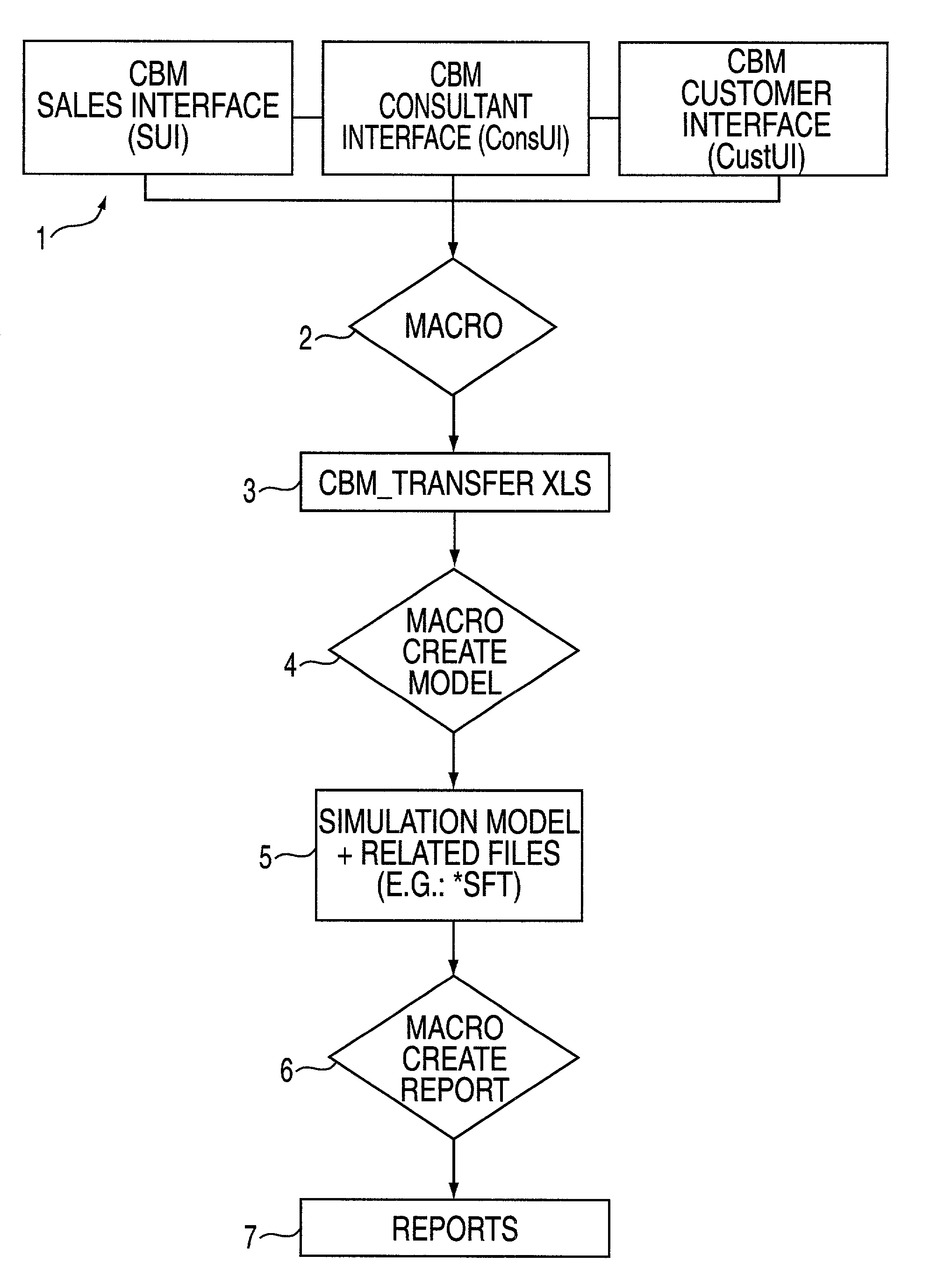
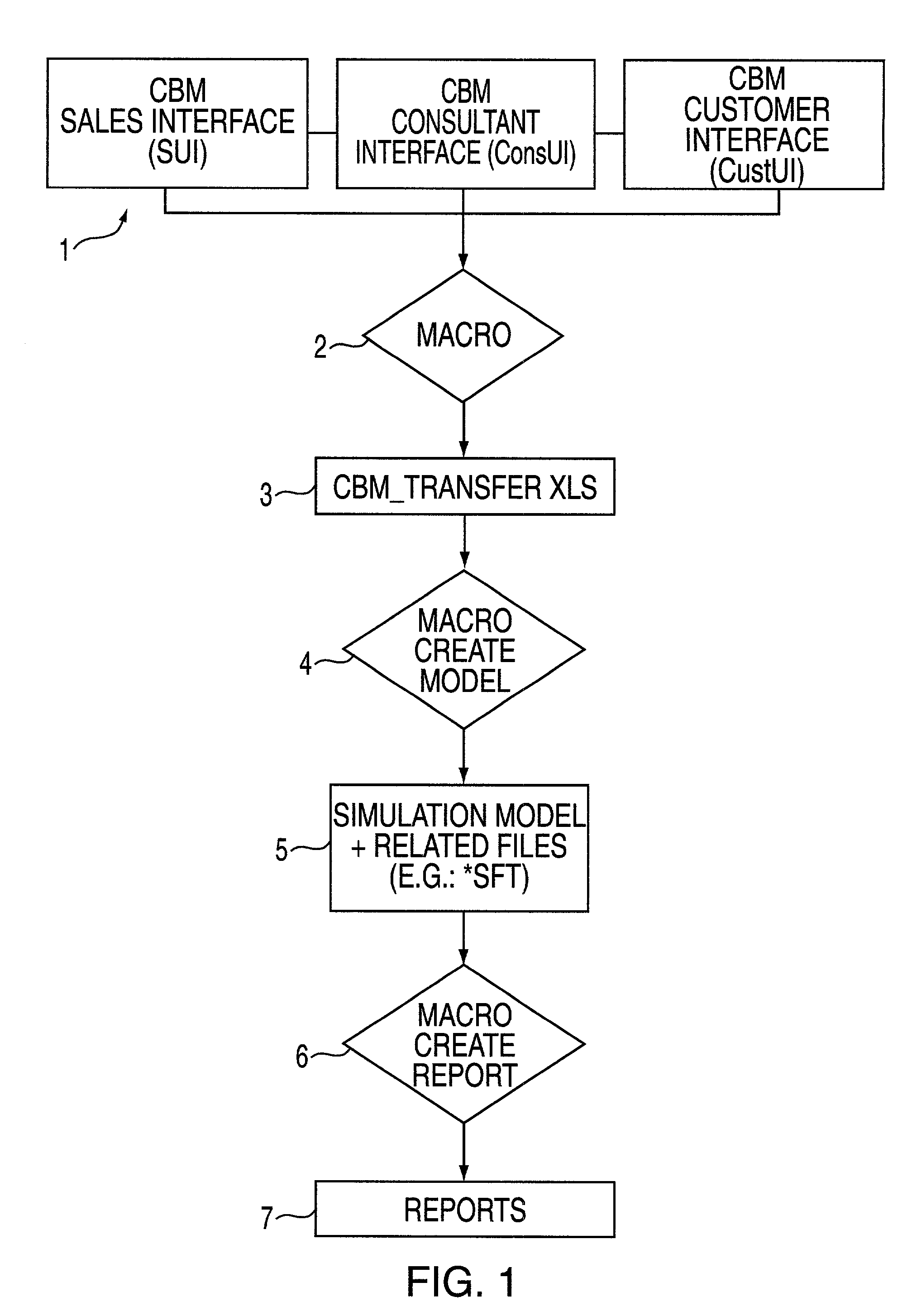
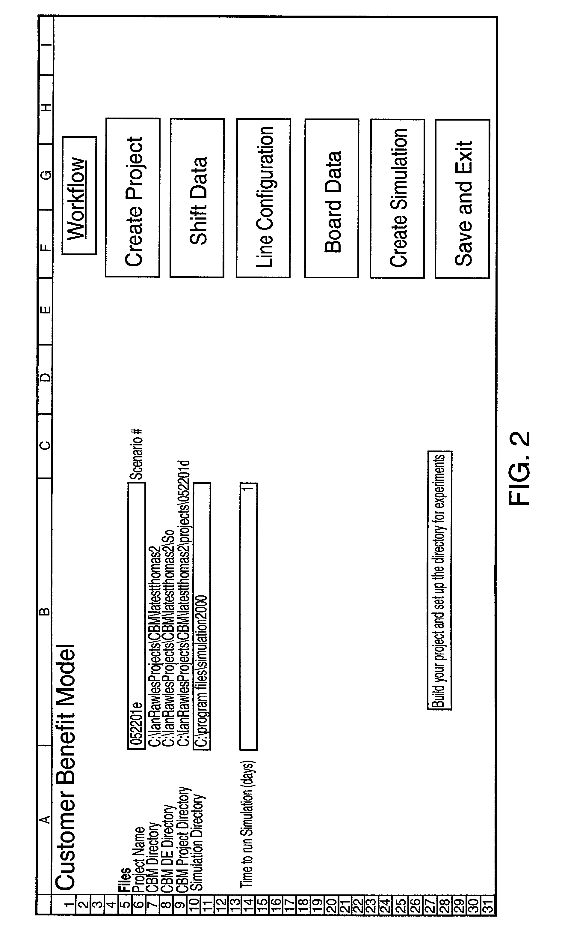
[0054]The present invention provides, among other things, tools and methods that enable quick and easy modeling and simulation of production assembly lines without the need to spend days or weeks building simulation models. It is particularly well-suited for use in modeling electronic component assembly production lines. Of course, it is also useful in modeling other assembly and manufacturing processes. Because the present invention enables quick, efficient modeling that typically can be performed in approximately 30 minutes or less, it is an ideal tool for use by electronics assembly equipment salespersons, as well as consultants and customers.

[0055]In accordance with the present invention, a consultant, sales person, customer, or an assembly line designer can quickly perform sophisticated simulations on a computer by inputting or selecting simple designer computer representations, e.g., designer objects, which represent particular pieces of equipment that are used in an assembly ...


PUM


Abstract

Methods and tools for quickly and accurately performing complex customer benefit modeling for an electronic components assembly system are disclosed. In one embodiment, predefined user interfaces allow a consultant, customers, salespersons, or line designers to input a line configuration by selecting from a list predefined objects that represent specific line components. In addition, the user inputs other line configuration data specific to the line being configured. The information contained in the user interface is extracted for use a discrete event simulator. Templates for simulation objects may be created in advance and populated with data from the input interface. A simulation is built and run. Simulation results may be exported to an output means, which may allow for custom generated reports. The reporting means may include a means for allowing customer specific information and data to be inputted.

Description

CROSS-REFERENCE TO RELATED APPLICATIONS[0001]This applications claims the benefit for purposes of priority, under 35 U.S.C. §119(e), of U.S. Patent Application Ser. Nos. 60 / 208,664, filed Jun. 1, 2000, and 60 / 280,679 filed Mar. 30, 2001, the contents of which are herein incorporated by reference in their entirety.COMPUTER PROGRAM LISTING APPENDIX[0002]This application incorporates by reference in its entirety a computer program listing appendix containing the source code listings which were described in the patent application at the time of filing and which have now been reproduced on compact disc. The compact disc contains the file entitled, “APPENDIX (Source Code)” that was created on Feb. 17, 2005 and encompasses 213 kilobytes.FIELD OF THE INVENTION[0003]The present invention relates in general to the field of electronics assembly systems and, in particular, to tools and methods for customer benefit modeling for purposes of electronics assembly system configurations.BACKGROUND OF...

Claims


Application Information

Patent Timeline
Patent Type & Authority Patents(United States)
IPC IPC(8): G06F7/48G06F9/45G05B19/418G06F9/455G06F17/00G06Q10/04G06Q10/06G06Q30/02
CPCG05B19/41885G06Q30/0283G06Q10/04G06Q10/06G06Q10/063G06Q30/02G05B2219/32338G05B2219/32343G05B2219/32352G05B2219/32359G05B2219/34038Y02P90/02
Inventor NGUYEN, TUANDUCK, ANTHONY PETERRAWLES, IANMAIR, THOMASGRAY, ROBERT
Owner SIEMENS ELECTRONICS ASSEMBLY SYST LLC
Why Eureka
Try Eureka