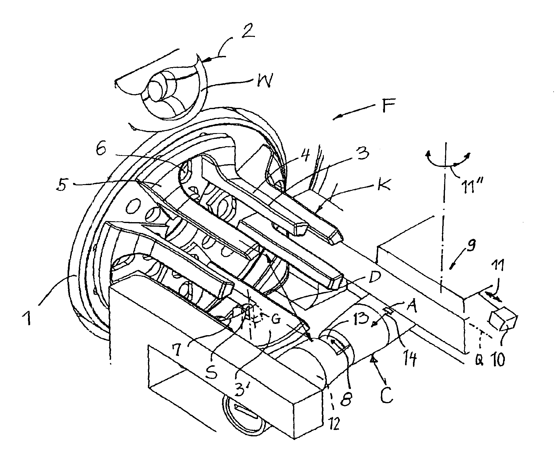
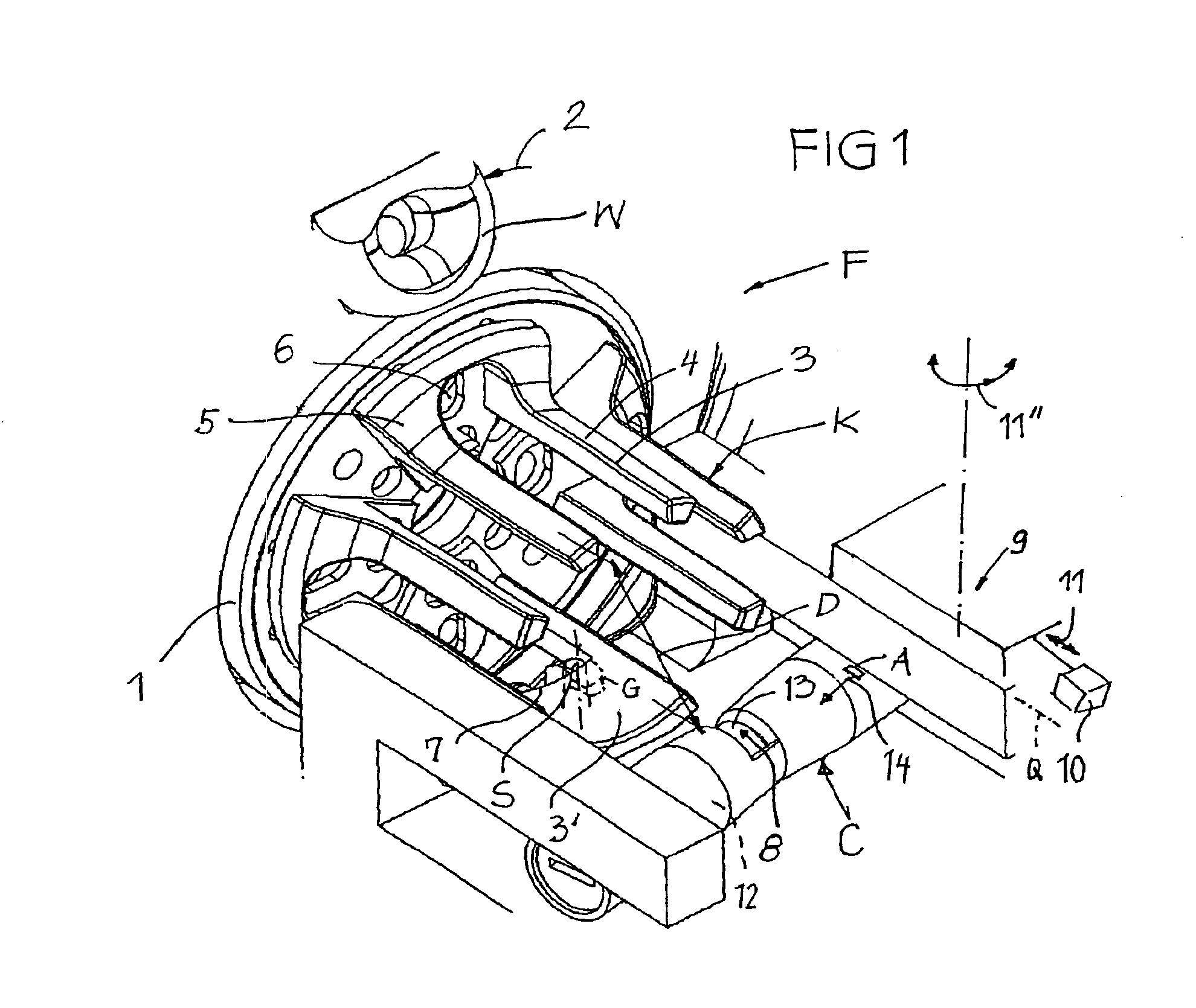
[0006]The combination of a small diameter storage body and a stop element which axially is moved into the stop position exclusively by the advancing motion of the windings allows utilization of the yarn feeding device substantially without disturbances, even in the case of high pick frequencies and / or high pick speeds and even with delicate yarn material. The small diameter storage body significantly reduces the ballooning effect or the
kinetic energy intermediately stored in a yarn
balloon, respectively, such that very high insertion speeds, and in particular short insertion times, can be achieved without excessive
mechanical load for the yarn. The small diameter storage body, however, needs a large number of windings for each pick. Mechanical disturbances of the movements of the windings on the storage body by the stop element should be avoided. This prerequisite is fulfilled when the stop element is moved exclusively axially into the stop position by the windings. The stop element does not need a drive for this movement. The stop element is taken along with the windings and follows the advancing movements of the windings with minimum or even no
mechanical resistance, which advancing movement of the windings is generated in a suitable way by the winding process, i.e. the stop element is dragged by the windings. Since the axial movement of the stop element into the stop position does not need any control from outside or from inside, the drive of the stop element only has to control the precise engagement of the stop element between the windings and to release disengagement again later substantially in the radial direction. In the combination, these features result in a
synergy effect leading to high
operational reliability even in the case of high yarn speed and / or short pick times and / or high pick frequencies. A small diameter storage body means a storage body which has a significantly smaller outer diameter in contradiction to the conventional tendency of feeding devices having a yarn length measuring function. In feeding devices having a yarn length measuring function, a large storage body is provided to have as few windings as possible on the storage body for each pick and also to have only an axial short yarn supply on the storage body.
[0007]A conventional controlled yarn clamp may, under certain conditions, not be good enough to cope with high pick speeds and to precisely start the pick in
adaptation to the weaving machine cycle. For this reason, the yarn clamp is equipped with a quick opening mechanism to assist in the positive effects of the small diameter storage body and of the stop element which is moved only by the windings into the stop position. The yarn clamp in this case is able to start the pick at a precisely predetermined point in time and particularly rapidly, e.g. within only a few milliseconds or even in a shorter period of time.
[0008]Expediently, the small outer diameter of the storage body defines a curvature of the circumference of the storage surface which at least substantially corresponds with the natural capability of natural, synthetic or compound yarn material to store a smallest unforced curvature. The yarn windings will lie relatively powerless, relaxed and in good order on the storage body. The rapid withdrawal of the yarn from this very small outer diameter storage body then only leads to a minimum ballooning effect. The result of the natural capability of the yarn to store a smallest unforced curvature means a certain bent yarn found when a free yarn section first is bent on a
smooth surface to a very small loop and is then released. This loop expands somewhat but maintains then a residual curvature. This residual curvature is used as a
guideline for
dimensioning the outer diameter of the storage body. Astonishingly, it has been found that different yarn qualities and different yarn materials with very few exceptions develop very similar unforced residual curvatures and for that reason can be processed well on the small diameter storage body.
[0011]Expediently, the stop element is connected by a hinge with a radial adjustment drive provided axially stationarily. The radial adjustment drive adjusts the stop element in a precisely timed manner and reliably into engagement in front of the just arriving yarn winding exiting from the winding element. The hinge or the bending section offers the necessary degree of freedom for the stop element thanks to which the stop element will be brought into the stop position only by the advance movement of the windings on the storage body substantially without any counter force.
[0014]Catching the yarn in the stop position of the stop element causes the undesirable stretching effect or
whiplash effect due to the momentary deceleration of the
mass of the yarn. As a counter measure it is particularly expedient to associate an
impact damper to the stop element in the stop position for alleviating / moderating the stretching effect or the
whiplash effect. That measure reduces the danger of a yarn breakage considerably. The
impact damper dissipates energy by resiliently giving way. The energy meant is introduced by the decelerated yarn into the stop element. The stop for the stop element may move e.g. counter to a
spring force over a small travelling
stroke either in the axial direction, in an inclined direction or in a circumferential direction of the storage body, respectively, in order to dissipate the energy. The stop element even may be elastically deformable in itself in order to carry out the
impact damping effect as soon as the yarn is stopped abruptly when the stop element has reached the stop.
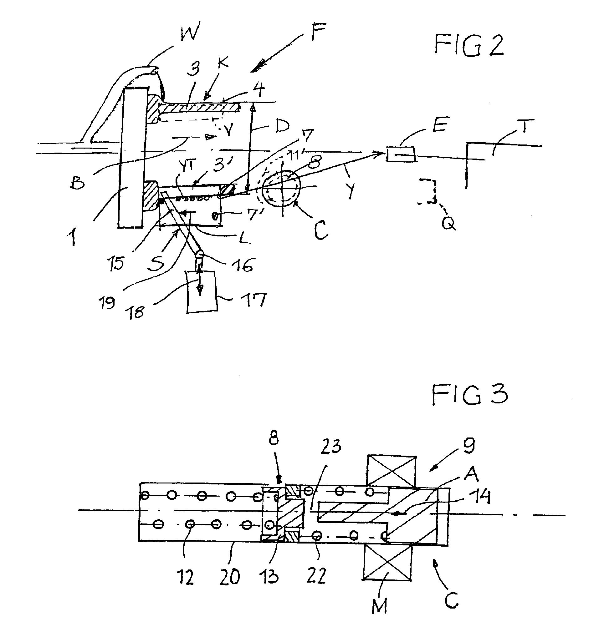
[0015]In order to precisely control and predetermine the point in time of the start of the pick by the yarn clamp, it is expedient to open the yarn clamp by an actuating solenoid and to provide for the armature of the actuating solenoid a certain idle
stroke in relation to the clamping element of the yarn clamp. As soon as the actuating solenoid is excited, the armature uses the idle
stroke to first accelerate free from the
mass of the clamping element and the oppositely directed
spring force, and first to build up a lot of
kinetic energy during the acceleration, and then to displace the clamping element abruptly into the passive position after the idle stroke has been passed with
high acceleration and / or
high kinetic energy. In this way a yarn clamp opening time may be reached which is in the range of only a few milliseconds or even shorter.


