Endoscope and endoscope system with optical phase modulation member

a technology of optical phase modulation and endoscope, which is applied in the field of electronic endoscope systems, can solve the problems of deteriorating optical transfer function restoring means, affecting the brightness of instruments, and affecting the quality of optical transfer functions, etc., and achieves the effect of high-resolution images

Inactive Publication Date: 2006-01-10
OLYMPUS CORP
View PDF10 Cites 78 Cited by
  • Summary
  • Abstract
  • Description
  • Claims
  • Application Information

AI Technical Summary

Benefits of technology

[0032]Accordingly, an object of the present invention is to provide an endoscope system capable of offering an extended depth of field and producing a high-resolution image.

Problems solved by technology

This poses a problem in that brightness is degraded.
Moreover, diffraction effects impose a theoretical limit on the depth of field.
However, U.S. Pat. No. 5,748,371 and Japanese Unexamined Patent Application Publication No. 2000-5127 describe that: when the technology for offering an extended depth of field by including an optical phase modulation mask in an optical system is implemented in an endoscope, an optical transfer function restoring means is needed for restoring an optical transfer function deteriorated due to the inclusion of the optical phase modulation mask and producing a high-resolution image.
Therefore, when an endoscope having an optical phase modulation mask included in an optical system is employed, a resolved image cannot be produced.
Thus, the endoscope system cannot guarantee interchangeability between the endoscope having the optical phase modulation mask and an endoscope not having it.
The resultant circuitry is complex and large in size.
This invites a great increase in the size of a main body of the endoscope and deteriorates maneuverability thereof.
For example, when a rotationally asymmetrical optical element is adopted as an optical phase modulation mask, if an error occurs during assembling during which the optical element is disposed to rotate about an optical axis, the optical element cannot be mated with an optical transfer function restoring means.
This poses a problem in that a high-resolution image cannot be produced.
However, this solution has a drawback that the inclusion of the means leads to a complex imaging optical system.

Method used


Image

  • Endoscope and endoscope system with optical phase modulation member
  • Endoscope and endoscope system with optical phase modulation member
  • Endoscope and endoscope system with optical phase modulation member

Examples


first embodiment

[0072](First Embodiment)

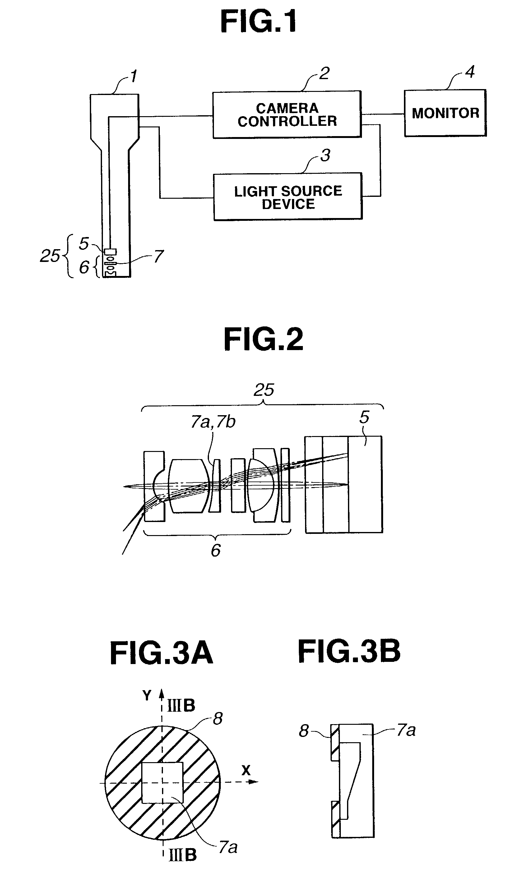
[0073]FIG. 1 to FIG. 14 show a first embodiment of an endoscope system in which the present invention is implemented.

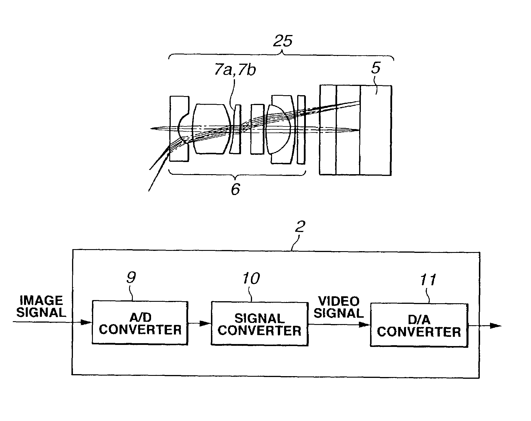
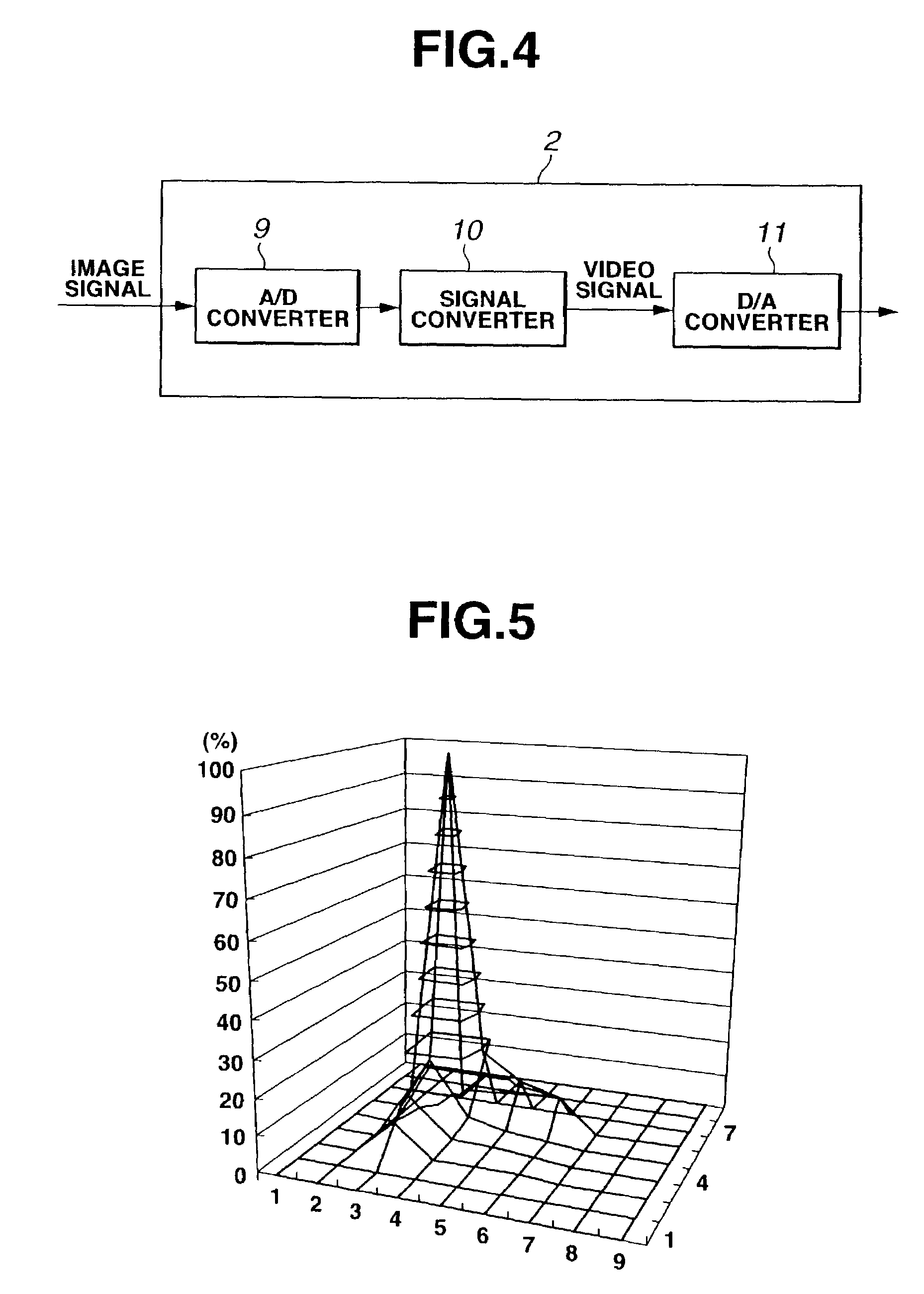
[0074]FIG. 1 schematically shows the configuration of an endoscope system in accordance with the first embodiment. FIG. 2 is an explanatory diagram showing the components of an imaging unit that includes an optical phase modulation mask according to the first embodiment. FIG. 3A and FIG. 3B are explanatory diagrams schematically showing the structure of an exit pupil modulation element that includes an aperture stop member according to the first embodiment. FIG. 4 is a block diagram showing the components of a camera controller (signal processing unit) included in the first embodiment. FIG. 5 to FIG. 8 are explanatory diagrams showing the results of simulation for producing a point image using the imaging unit, which includes the exit pupil modulation element according to the first embodiment, with a distance to an object set to 71 mm, 13.5 mm,...

second embodiment

[0103](Second Embodiment)

[0104]Next, a second embodiment will be described. The present embodiment has the same basic components as those of the first embodiment. The description of the components will therefore be omitted. The shape of an exit pupil modulation element different from the one employed in the first embodiment, and a signal processing circuit incorporated in a camera controller will be described mainly.

[0105]FIG. 15 to FIG. 20 show the second embodiment of an endoscope system in which the present invention is implemented.

[0106]FIG. 15 to FIG. 18 show the results of simulation for producing a point image using an imaging unit, which includes an exit pupil modulation element according to the second embodiment, with a distance to an object set to 71 mm, 13.5 mm, 7.2 mm, and 4 mm. FIG. 19 shows the results of simulation for calculating a response derived from an optical transfer function characterizing the imaging unit, which includes the exit pupil modulation element acco...


PUM


Abstract

An endoscope system consists mainly of: an endoscope having a solid-state imaging device and an objective optical system that converges an object image on said solid-state imaging device; and a signal processing unit that processes an image signal produced by the endoscope so as to produce a video signal. The objective optical system includes an optical phase modulation member. The optical phase modulation member exhibits a response of 0.2 or more derived from an optical transfer function relative to a spatial frequency on the solid-state imaging device determined based on the Nyquist theorem, that is, a Nyquist frequency, over a wider range of distances than a depth of field offered by an objective optical system not having the optical phase modulation member.

Description

[0001]This application claims the benefit of Japanese Application No. 2001-401830 filed on Dec. 28, 2001, the contents of which are incorporated by reference.BACKGROUND OF THE INVENTION[0002]1. Field of the Invention[0003]The present invention relates to an electronic endoscope system, or more particularly, to an electronic endoscope system in which a plurality of types of endoscopes that are different from one another in terms of specifications or usage is employed and an object image is viewed through a monitor.[0004]2. Description of the Related Art[0005]Endoscopes that permit observation of an intracorporeal region that is invisible with naked eyes are, as already known, widely used for diagnosis or cure in the field of medicine. In recent years, an electronic endoscope that includes a CCD or any other solid-state imaging device, which converts an object image into an electric signal, and that permits observation of an object by means of a monitor has become popular. As the elec...

Claims


Application Information

Patent Timeline
Patent Type & Authority Patents(United States)
IPC IPC(8): A61B1/04G02B26/06A61B1/00G02B23/24A61B1/05G02B23/26H04N5/225H04N7/18
CPCH04N5/2254A61B1/05H04N2005/2255H04N23/555H04N23/80
Inventor KUMEI, KAZUHIROSUGA, TAKESHIYABE, HISAOHIRAI, TSUTOMUHIROYA, JUNISHII, HIROSHI
Owner OLYMPUS CORP
Why Eureka
Try Eureka