Motor

a motor and motor technology, applied in the direction of rotating magnets, synchronous machines with stationary armatures, windings, etc., can solve the problems of reducing efficiency, observing waveform distortion in the counter electromotive voltage, and not knowing the actual application of the disclosed methods to automobiles. , to achieve the effect of increasing torque, increasing size, and increasing waveform distortion

Inactive Publication Date: 2006-01-10
PANASONIC CORP
View PDF24 Cites 32 Cited by
  • Summary
  • Abstract
  • Description
  • Claims
  • Application Information

AI Technical Summary

Benefits of technology

[0033]Furthermore, since the widths of the slot opening and stator teeth are set as described above, the waveform of the counter electromotive voltage will be approximated to a sine wave with a large torque as compared to a conventional motor in the same size, and an aluminum wire will then be used for the coil instead of a copper wire without increasing the size of the above-described motor and without increasing distortions in the waveform of the counter electromotive voltage as compared to the conventional motor.

Problems solved by technology

However, examples of actual application of the disclosed methods to automobiles have not been known.
On the other hand, waveform distortions are observed in the counter electromotive voltage.
A large waveform distortion in the counter electromotive voltage increases eddy current and thus iron loss, which lowers the efficiency.
Meanwhile, if coils for a motor as disclosed by Japanese Patent Laid-Open Publication No. 2000-245085, a typical commutator motor and a brushless motor are simply changed from copper wires to aluminum wires, the conductor loss could be great because the resistivity of the aluminum wire is higher than copper wire by about 60%.
Meanwhile, in order to keep the loss from increasing, the motor size must be increased, and in either way, the method remains to be disadvantageous in terms of energy and resource conservation.

Method used


Image

  • Motor
  • Motor
  • Motor

Examples


embodiment 1

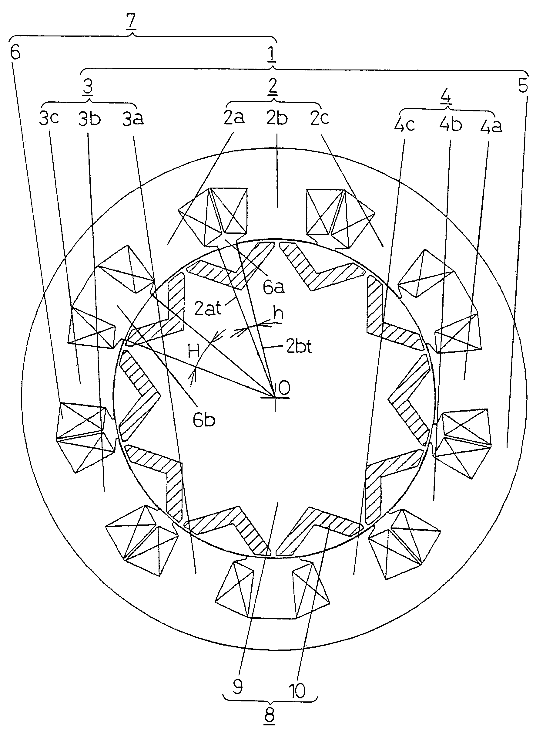
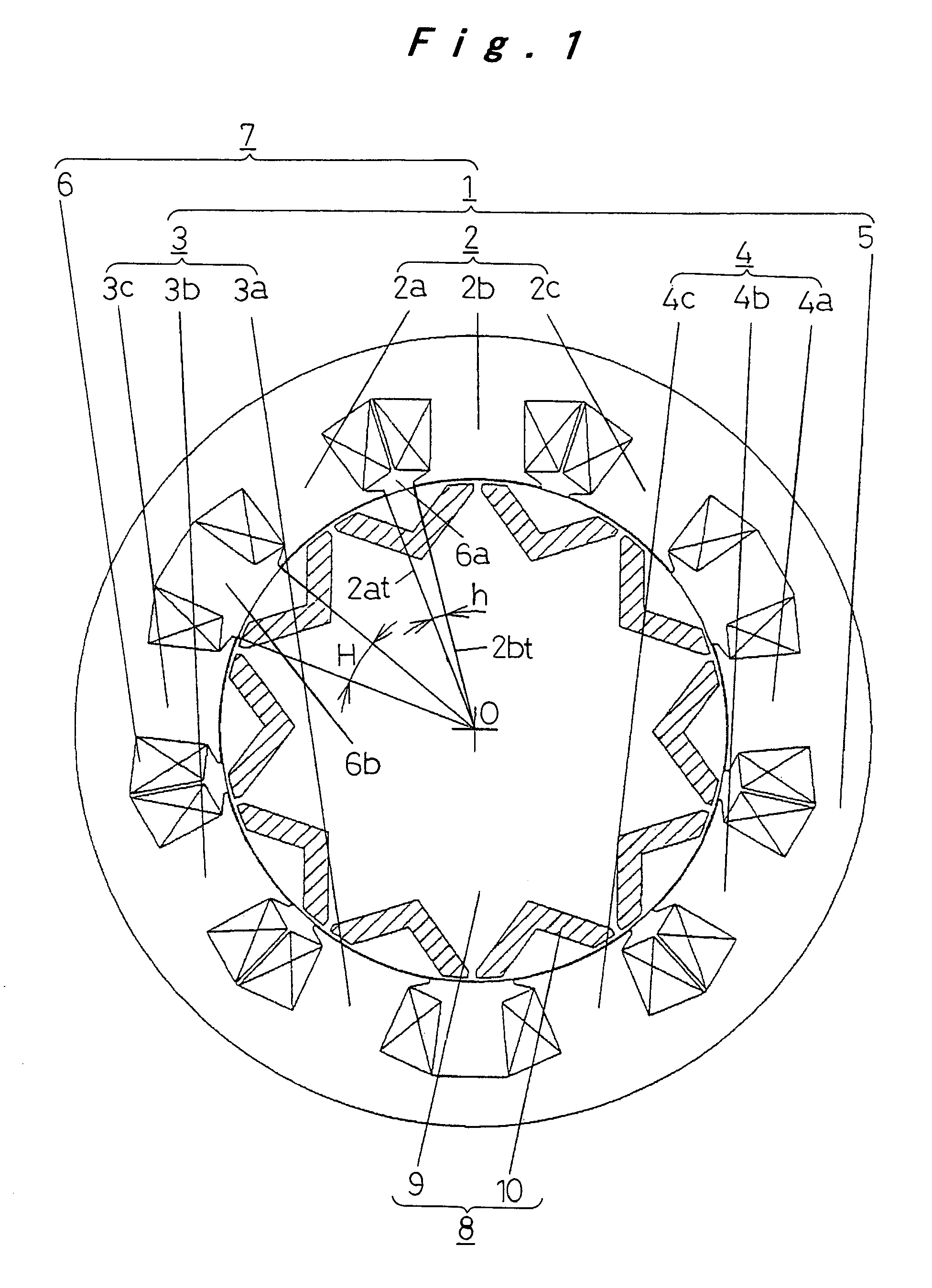
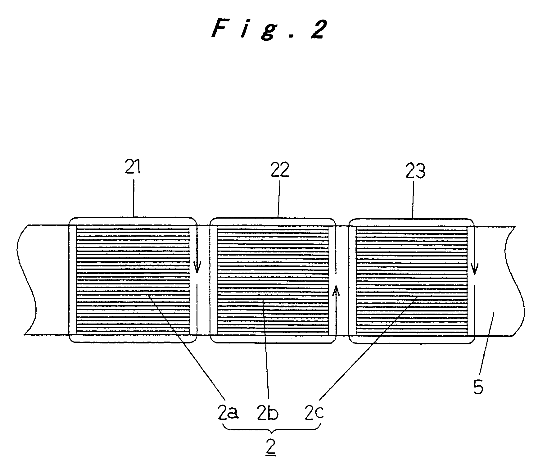
[0052]FIGS. 1 to 4D are views for use in illustration of a motor according to Embodiment 1 of the present invention. FIG. 1 is a sectional view of a main part in a plane orthogonal to the central axis of the rotating shaft for the purpose of illustrating the motor main part, FIG. 2 is a development for use in illustration of the direction in which coils are wound around stator teeth, FIG. 3 is a view for use in illustration of how coils wound around stator teeth are connected, and FIGS. 4A to 4D are sectional views of the shapes of permanent magnets embedded in rotor cores and other examples of the rotor cores.

[0053]In FIG. 1, a stator core 1 includes a plurality of stator teeth 2a, 2b, 2c, 3a, 3b, 3c, 4a, 4b, and 4c, and a stator yoke 5 that connects the stator teeth 2a to 4c at one end. A coil 6 is wound around each of the stator teeth 2a to 4c, and the stator core 1 and the coils 6 form a stator 7.

[0054]The stator teeth 2a to 4c are divided into three groups in total, each of whi...

embodiment 2

[0071]FIGS. 5 to 7 are views for use in illustration of a motor according to Embodiment 2 of the present invention, FIG. 5 is a top view of a stator core, FIG. 6A is a partially enlarged view showing a part of FIG. 5 being enlarged, FIG. 6B is a partially enlarged view showing a part of a modification of the stator core being enlarged, and FIG. 7 is a enlarged view showing a modification of the tip end of a stator tooth.

[0072]In FIG. 5, a stator core 41 includes stator teeth 42a, 42b, 42c, 43a, 43b, 43c, 44a, 44b, and 44c, and a stator yoke 45 that connects these stator teeth 42a to 44c at one end. Similarly to Embodiment 1, the stator teeth 42a, 42b, and 42c form a group 42, the stator teeth 43a, 43b, and 43c form a group 43, and the stator teeth 44a, 44b, and 44c form a group 44. The coils (not shown) wound around the stator teeth in the groups 42, 43, and 44 form U, V, and W phases, respectively. Similarly to Embodiment 1 described above, the directions in which coils are wound a...

embodiment 3

[0083]FIGS. 8 and 9 are views for use in illustration of a motor according to Embodiment 3 of the present invention. FIG. 8 is a schematic sectional view of a stator core and a rotor opposing the inner circumferential surface of the stator core taken along a plane perpendicular to the central axis of the rotating shaft and FIG. 9 is a partially enlarged view showing a stator core being enlarged for the purpose of showing the shape of stator teeth forming the stator core.

[0084]In FIG. 8, a stator core 71 includes stator teeth 72a, 72b, 72c, 73a, 73b, 73c, 74a, 74b, and 74c, and a stator yoke 75, and similarly to the Embodiment 1 described above, the plurality of stator teeth 72a to 74c are divided into three groups 72, 73, and 74. In the same group, coils 76 are wound around adjacent stator teeth in opposite directions to each other. The stator core 71 and the coils 76 arranged around the stator teeth 72a to 74c of the stator core 71 form the stator 77. There is a small gap between t...


PUM


Abstract

In a permanent magnet-embedded, concentrated winding motor, plurality of stator teeth are divided into, for example, three groups that include a plurality of adjacent stator teeth having coils wound around and that are provided with voltage in phase that are set as one group. Coils are wound in opposite directions around adjacent stator teeth in the same group, while the relation between the angle h of a slot opening between adjacent stator teeth of the same group and the angle H of a slot opening formed between adjacent stator teeth of different groups satisfies h<H≦3h.

Description

TECHNICAL FIELD[0001]The present invention relates to a motor suitably applied to a vehicle such as a pure electric vehicle (PEV), a hybrid electric vehicle (HEV), and a fuel cell electric vehicle (FCEV), and also to a motor suitably applied to a home electrical appliance, a robot, and the like.BACKGROUND ART[0002]As motor technology for use in a vehicle and the like as described above, Japanese Patent Laid-Open Publication No. 2000-245085 discloses the use of a concentrated winding, magnet-embedded type motor.[0003]The example disclosed by Japanese Patent Laid-Open Publication No. 2000-245085 will be described in conjunction with FIG. 17. FIG. 17 is a sectional view of a main part of a motor including a concentrated winding stator made of a stator core, a plurality of stator teeth with coils wound therearound, and a magnet-embedded type rotor. The section is a plane orthogonal to the central axis of the rotating shaft of the motor.[0004]As shown in FIG. 17, the stator core 145 incl...

Claims


Application Information

Patent Timeline
Patent Type & Authority Patents(United States)
IPC IPC(8): H02K1/00H02K1/14H02K3/02H02K21/16H02K29/03
CPCH02K1/146H02K29/03H02K21/16H02K3/02
Inventor KADOYA, NAOYUKIKONDO, YASUHIROTAGOME, MASAKITAMAKI, SATOSHI
Owner PANASONIC CORP
Why Eureka
Try Eureka