Random antenna array interferometer for radio location

an antenna array and radio location technology, applied in direction finders, directions using radio waves, instruments, etc., can solve the problems of preventing coherent demodulation, preventing the implementation of sub-meter precision time-of-arrival location methods, and determining precise (1 m resolution) positions of wildlife radio transmitters. to achieve the effect of reducing noise power

an antenna array and radio location technology, applied in direction finders, directions using radio waves, instruments, etc., can solve the problems of preventing coherent demodulation, preventing the implementation of sub-meter precision time-of-arrival location methods, and determining precise (1 m resolution) positions of wildlife radio transmitters. to achieve the effect of reducing noise power

US6985107B2Inactive Publication Date: 2006-01-10LOTEK WIRELESS

Image

  • Random antenna array interferometer for radio location
  • Random antenna array interferometer for radio location
  • Random antenna array interferometer for radio location

Examples


Embodiment Construction

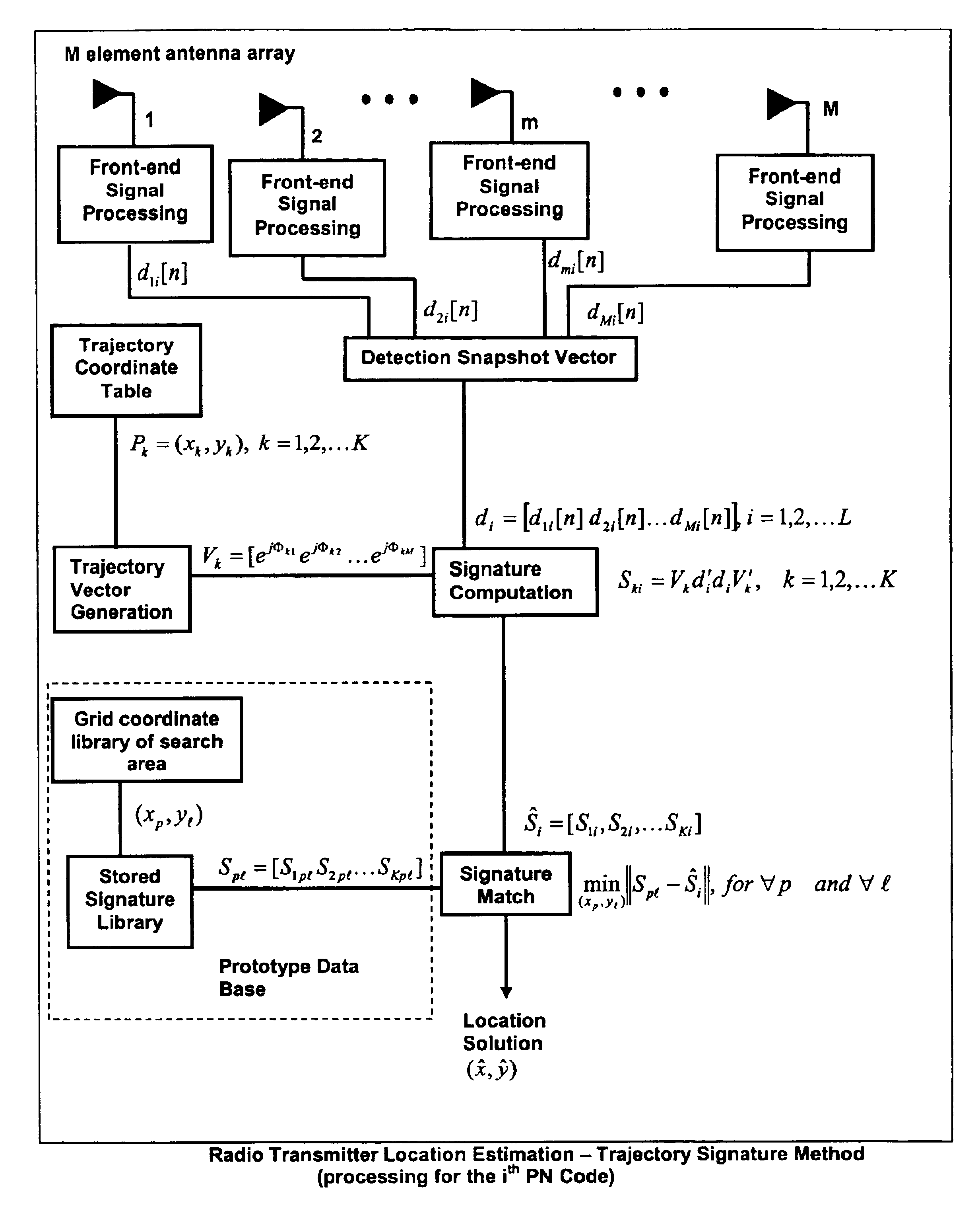
[0016]FIGS. 1 to 5 describe the invention with respect to orthogonal sub-space projection of an individual detection snapshot vector taken from a CDMA enabled transmitter. FIG. 6 describes signature matching as an alternative to orthogonal sub-space projection. FIGS. 7 through 9 provide a generalization of both methods to non-CDMA signal localization.

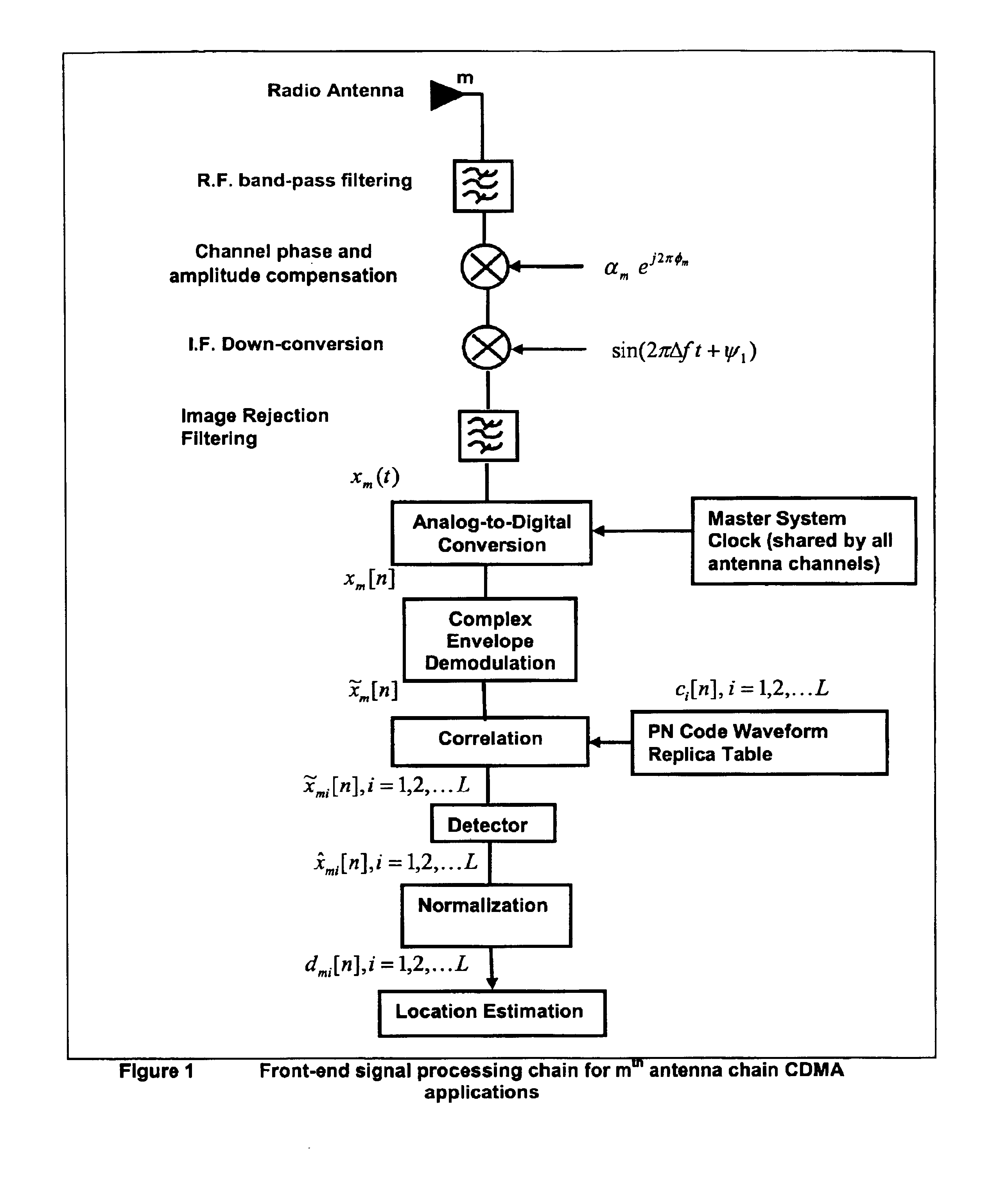
[0017]FIG. 1 is a flow chart showing the front-end signal processing chain for mth antenna chain CDMA applications.

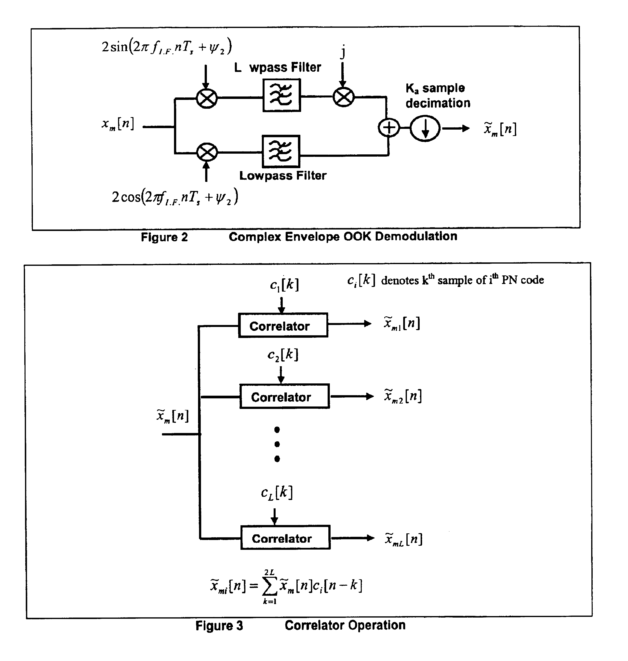
[0018]FIG. 2 is a block diagram of showing Complex Envelope OOK Demodulation, which appears as a single block in the flow chart of FIG. 1.

[0019]FIG. 3 is a block diagram showing the Correlation function used to decouple individual CDMA transmitter signals from one another.

[0020]FIG. 4 is an expanded view of the Normalization block in the flow chart of FIG. 1.

[0021]FIG. 5 is a flow chart showing the location estimation based on pure phase angle of arrival information for a single pseudo random PN code decoupled from other CD...


PUM


Abstract

This invention relates to a method and system for the radio location of CDMA and non-CDMA enabled transmitters within a reception zone. The invention exploits the superposition of antenna patterns that create complex and asymmetrical interference structures at very small scales. By randomly distributing a random antenna array of M elements across a two or three-dimensional surface, fine scale interference structures on the scale of ¼ the carrier wavelength are generated. Once the minimum number of antennas are placed, additional antennas will not improve the resolution. Such interference structures when sampled at ⅛ the carrier wavelength or greater yields unique spatial patterns with respect to a given antenna array geometry and transmitter location. The invention incorporates signature recognition (matching) and orthogonal sub-space projection estimators to derive location estimates of a radio transmitter.

Description

FIELD OF THE INVENTION[0001]This invention relates to a method and system for the accurate localization of multiple radio frequency signals over a large area. The innovation presented here was developed in the context of miniature (<1 gram) wildlife tracking devices, but is generalized to the problem of locating either CMDA or non-CDMA transmitters.BACKGROUND[0002]Despite the revolutions represented by GPS technology and advanced direction-of-arrival algorithms (DoA), the problem of determining precise (<1 m resolution) positions of wildlife radio transmitters remains to date essentially unsolved. There are a number of reasons for this, principal among them being the low-duty cycle nature of the signals (required by practical energy / payload constraints), which prevents coherent demodulation. Payload constraints (<1 gram for small species of animals) also preclude the inclusion of ultra-precise clocks into transmitters which in turn prevents the implementation of sub-meter p...

Claims


Application Information

Patent Timeline
10 Jan 2006
Publication
US6985107B2
IPC
G01S3/02; G01S3/48
CPC
G01S3/48
Inventors
ANSON, PETER; NIEZGODA, GEORGE