Internal antenna

Inactive Publication Date: 2006-01-10
CANTOR FITZGERALD SECURITIES
View PDF15 Cites 118 Cited by
  • Summary
  • Abstract
  • Description
  • Claims
  • Application Information

AI Technical Summary

Benefits of technology

[0008]An advantage of the invention is that the antenna gain will increase as the matching improves, compared to a corresponding antenna according to the prior art. Thus it is possible, for example, to shorten the distance between the ground plane and the radiating plane proper by an amount corresponding to the antenna gain difference. This will result in an antenna having the same antenna gain but which is flatter, whic

Problems solved by technology

As the devices get smaller and smaller, the space for the antenna keeps shrinking, too, which means tighter requirements in antenna design.
If one keeps on reducing the size of the ground plane, it may at some point function as a radiator, thus changing the antenna characteristics in an uncontrolled manner.
A dis

Method used


Image

  • Internal antenna
  • Internal antenna
  • Internal antenna

Examples


Embodiment Construction

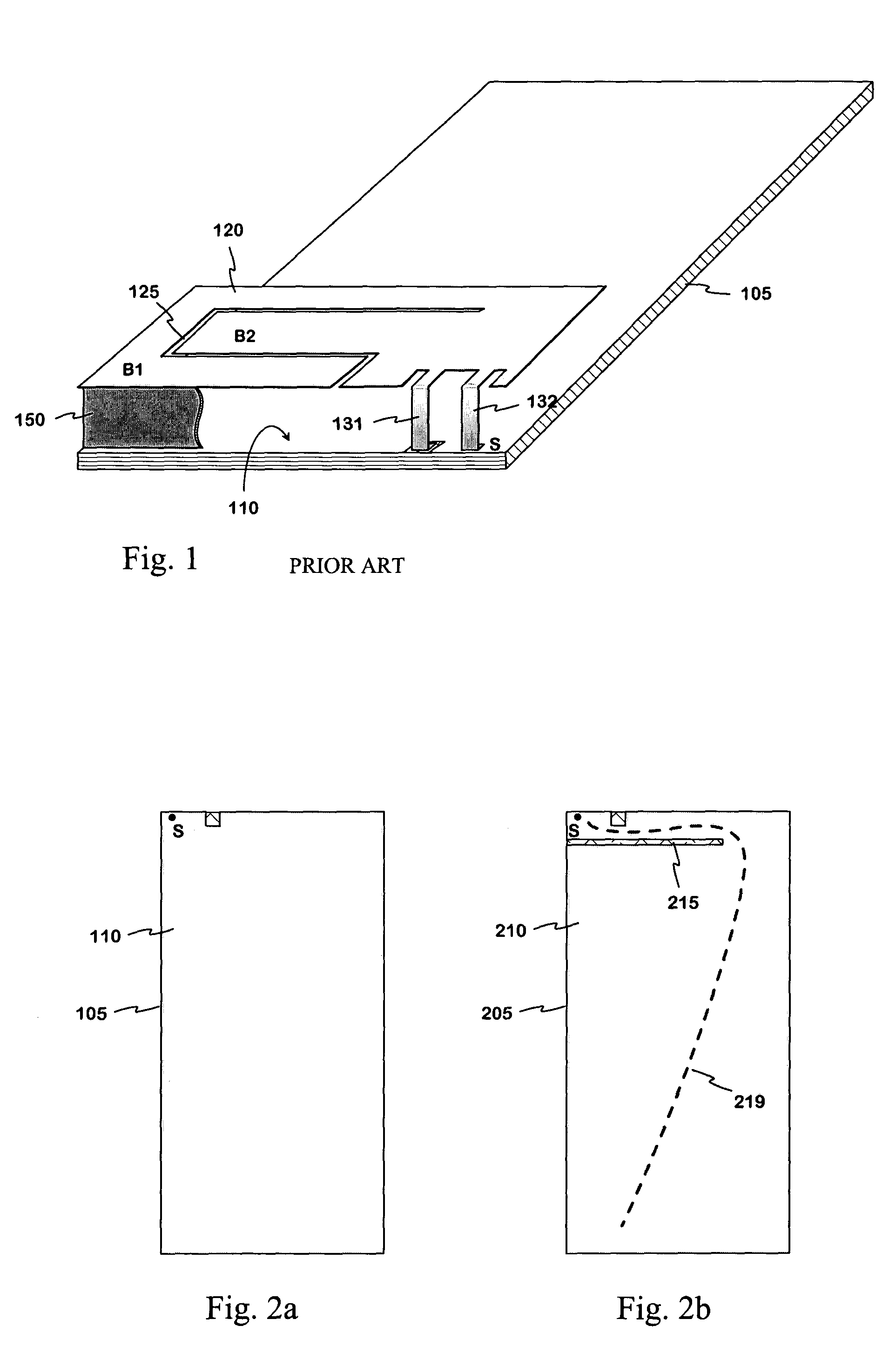
[0021]FIGS. 2a,b illustrate the principle of increasing the electrical length of the ground plane in accordance with the invention. FIG. 2a shows the circuit board 105 of the structure depicted in FIG. 1 as seen from the ground plane's side. At the upper left corner of the ground plane 110 there is the short-circuit point S for the radiating plane. As the ground plane has no patterns altering its shape, its electrical length, measured from the short-circuit point, is determined by the lengths of the sides of the rectangular plane. As the ground plane is relatively small, its electrical length is significant, because the ground plane may radiate at a frequency order of operating frequencies, like a branch of a dipole antenna.

[0022]FIG. 2b shows a printed circuit board 205 which is similar to the one described above except that there is now a slot 215 in the ground plane. The slot starts from the long side of the ground plane near the short-circuit point S and travels parallel to the ...


PUM


Abstract

An internal planar antenna for small radio apparatuses. The ground plane (310) of the planar antenna is shaped such that it improves the matching of the antenna. The shaping may be done by means of one or more slots (315, 316) in the ground plane. The slot suitably changes the electrical length of the ground plane as viewed from the short-circuit point (S) so that the ground plane will function as a radiator in an operating band of the antenna. Also the slot (331) in the ground plane can be arranged to function as an additional radiator in an operating band of the antenna. Antenna gain will increase as the matching is improved, and the upper band of a dual band antenna, for example, can be made broader.

Description

[0001]The invention relates to an internal planar antenna intended for small radio apparatuses. The invention also relates to a radio apparatus employing an antenna according to the invention.BACKGROUND OF THE INVENTION[0002]In antenna design, the space available is an important factor. A good-quality antenna is relatively easy to make if there are no size restrictions. In radio apparatuses, especially in mobile phones, the antenna is preferably placed within the covering of the device for convenience. As the devices get smaller and smaller, the space for the antenna keeps shrinking, too, which means tighter requirements in antenna design. Another factor contributing to this is that often an antenna has to be capable of operating in two or more frequency bands.[0003]An antenna with satisfactory characteristics which fits inside a small device is in practice most easily implemented as a planar structure: The antenna comprises a radiating plane and a ground plane parallel thereto. In ...

Claims


Application Information

Patent Timeline
IPC IPC(8): H01Q1/38H01Q1/24H01Q1/48H01Q5/00H01Q5/371H01Q9/04
CPCH01Q1/243H01Q1/48H01Q5/371H01Q9/0442H01Q9/0421
Inventor MIKKOLA, JYRKIANNAMAA, PETTERI
Owner CANTOR FITZGERALD SECURITIES
Why Eureka
Try Eureka