
LED bar array high addressable imaging in 2-dimensions

a high-addressable, 2-dimensional technology, applied in the field of printers, can solve the problems of increasing the spatial resolution of the xerographic print engine, the upper limit of the resolution that can be achieved, and the cost/performance trade-off to be considered, so as to achieve the effect of high-addressability techniques, reduced spot size, and image characteristics

Inactive Publication Date: 2006-01-10
XEROX CORP
View PDF22 Cites 9 Cited by
  • Summary
  • Abstract
  • Description
  • Claims
  • Application Information

AI Technical Summary

Benefits of technology

[0029]One advantage of the present invention resides in the identification, in real time, of image characteristics which are enhanced from selective altered exposure.
[0030]Another advantage of the present invention resides in the application of high addressability techniques to LED bars with their often inherently smaller spot sizes.
[0031]Another advantage of the present invention resides in the smoothing of edges, corners and / or intersections of output images.
[0032]Yet another advantage of the present invention resides in the ability to employ the sharp spot profiles available from an LED bar, for example, while enabling two-dimensional high addressable printing.
[0033]Still further advantages of the present invention will become apparent to those of ordinary skill in the art upon reading and understanding the following detailed description of the preferred embodiments.

Problems solved by technology

As a practical matter, the image transition positioning precision of these printers can be increased to an extent by increasing their spatial resolution, but the frequency responses of the photoreceptor / developer combinations that currently are available for xerographic printing usually impose an upper limit on the resolution that can be achieved.
Moreover, even when increased resolution is technically feasible, the additional resolution imposes further and potentially burdensome requirements on the optical and electrical design requirements of these printers, so there usually is a cost / performance tradeoff to be considered.
Specifically, the cost of xerographic print engines tends to escalate as their spatial resolution is increased because of the additional memory and bandwidth these printers require for faithfully rendering higher resolution bitmap images without sacrificing throughput.
It does not, however, solve the control problems that are encountered in existing printers because of the significant non-linearity of the way in which the spatial positioning and profiles of the transitions are handled.

Method used


Image

  • LED bar array high addressable imaging in 2-dimensions
  • LED bar array high addressable imaging in 2-dimensions
  • LED bar array high addressable imaging in 2-dimensions

Examples


Embodiment Construction

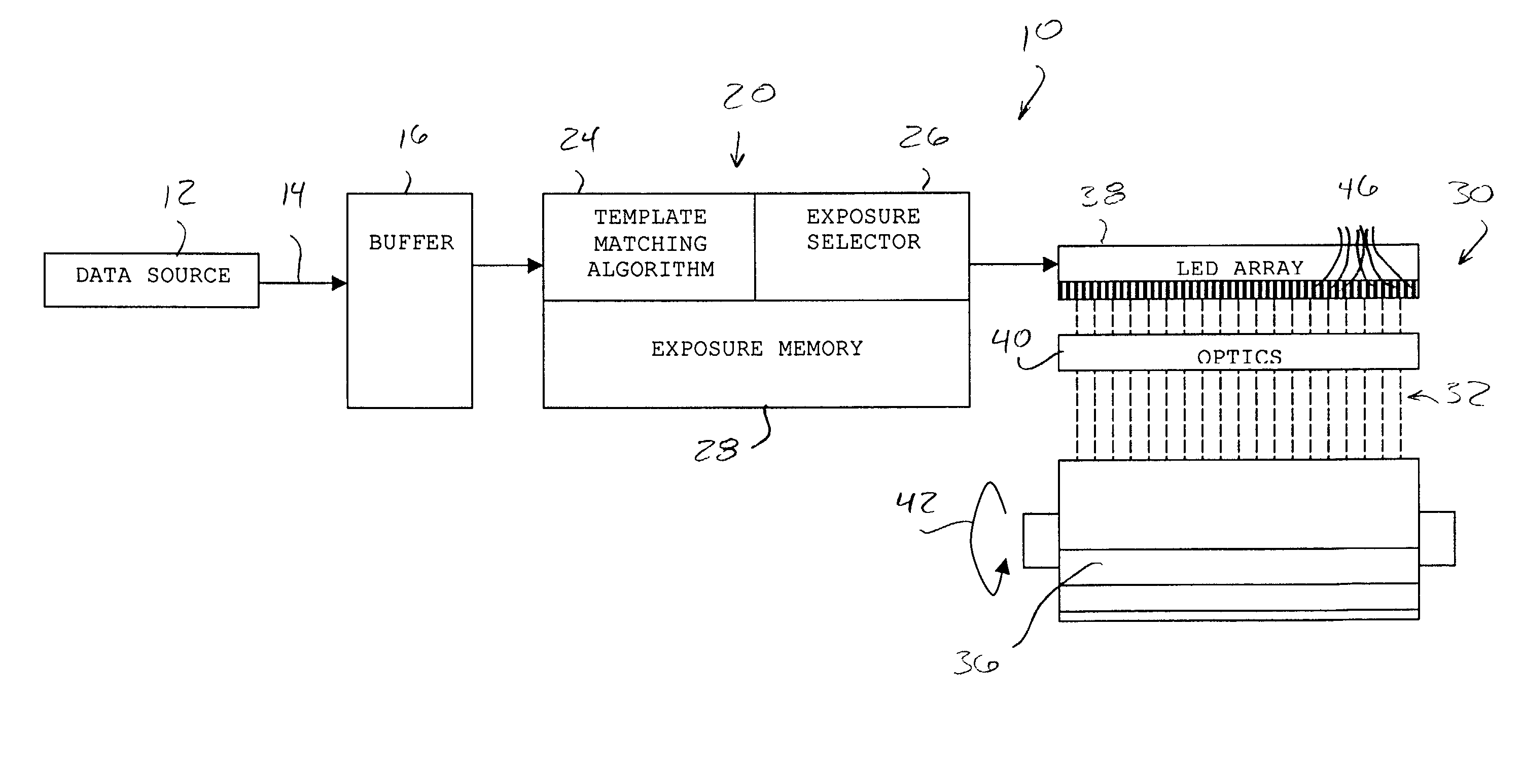
[0044]Turning now to the drawings, and at this point especially to FIG. 1, there is a xerographic print engine 10 (shown only in relevant part) having a data source 12 supplying pixels 14 representative of an image. The pixels 14 are optionally held in a buffer 16 before processing by an image rendering processor 20. In addition to conventional image rendering algorithms, the processor 20 includes an image characteristic identifier 24 which parses incoming pixels for particular image features such as lines, edges, text, corners and the like and identifies those pixels for special rendering as described below. A suitable image characteristic identifier 24 is the template matching algorithm illustrated, adaptable by those skilled in the art after the teachings herein are fully disclosed. Once identified, selector 26 selects particular pixels for variable exposure processing (more fully discussed below) and the varied exposure is determined, for example from memory 28.

[0045]Other rende...


PUM


Abstract

An imaging apparatus includes an input that receives a stream of image pixels such as high addressable bits, multiple bits per pixel or binary image bits representing an input image and a processor that processes and directs signals to an LED bar that selectively exposes areas of a photoreceptor. The exposed areas of the photoreceptor form a latent image, controlled by the processor, of areas of varied exposure based on surrounding pixels. The processor examines the pixels to determine an image structure beneficially adaptable to varied exposure and selects a pixel for varied exposure, such as increased or decreased exposure or altered timing to apply the pixel.

Description

BACKGROUND OF THE INVENTION[0001]This invention relates to printers and other optical display systems having high gamma, photosensitive recording media and, more particularly, to relatively inexpensive and easily implemented methods and means for increasing the precision with which these display systems spatially position edges and other types of transitions in the images they display.[0002]Many commercially available laser printers, as well as some electronic copiers, include imaging optics containing light emitting diode (LED) image bars or arrays. These devices place latent electrostatic images on previously charged xerographic photoreceptors. Typically, these photoreceptors have steeply sloped contrast vs. exposure characteristics (high gamma), together with well defined exposure thresholds (called the “xerographic threshold”), so they characteristically yield high contrast, bitmapped images (e.g., black and white). Some xerographic printers operate in a “write black” mode to op...

Claims


Application Information

Patent Timeline
Patent Type & Authority Patents(United States)
IPC IPC(8): G06K9/62B41J2/44B41J2/45B41J2/455G03G15/04G06K15/12H04N1/23
CPCG06K15/1247
Inventor BANTON, MARTIN E.
Owner XEROX CORP
Learn More