Location defined control of cellular system

a technology of cellular system and location, applied in the field of communication technology, can solve the problems of increasing bit error rate and reducing signal strength, and achieve the effects of reducing the frequency and reducing the frequency of handoffs, and increasing the overall system capacity

Inactive Publication Date: 2006-01-10
BELLSOUTH INTPROP COR
View PDF16 Cites 57 Cited by
  • Summary
  • Abstract
  • Description
  • Claims
  • Application Information

AI Technical Summary

Benefits of technology

[0026]Another object of the invention is to provide handoffs in a manner such that the incidence of dropped handoffs is reduced.
[0027]Another object of the invention is to provide handoffs

Problems solved by technology

This determination may be based on a diminishing signal strength and/or an increasing bit

Method used


Image

  • Location defined control of cellular system
  • Location defined control of cellular system
  • Location defined control of cellular system

Examples


Embodiment Construction

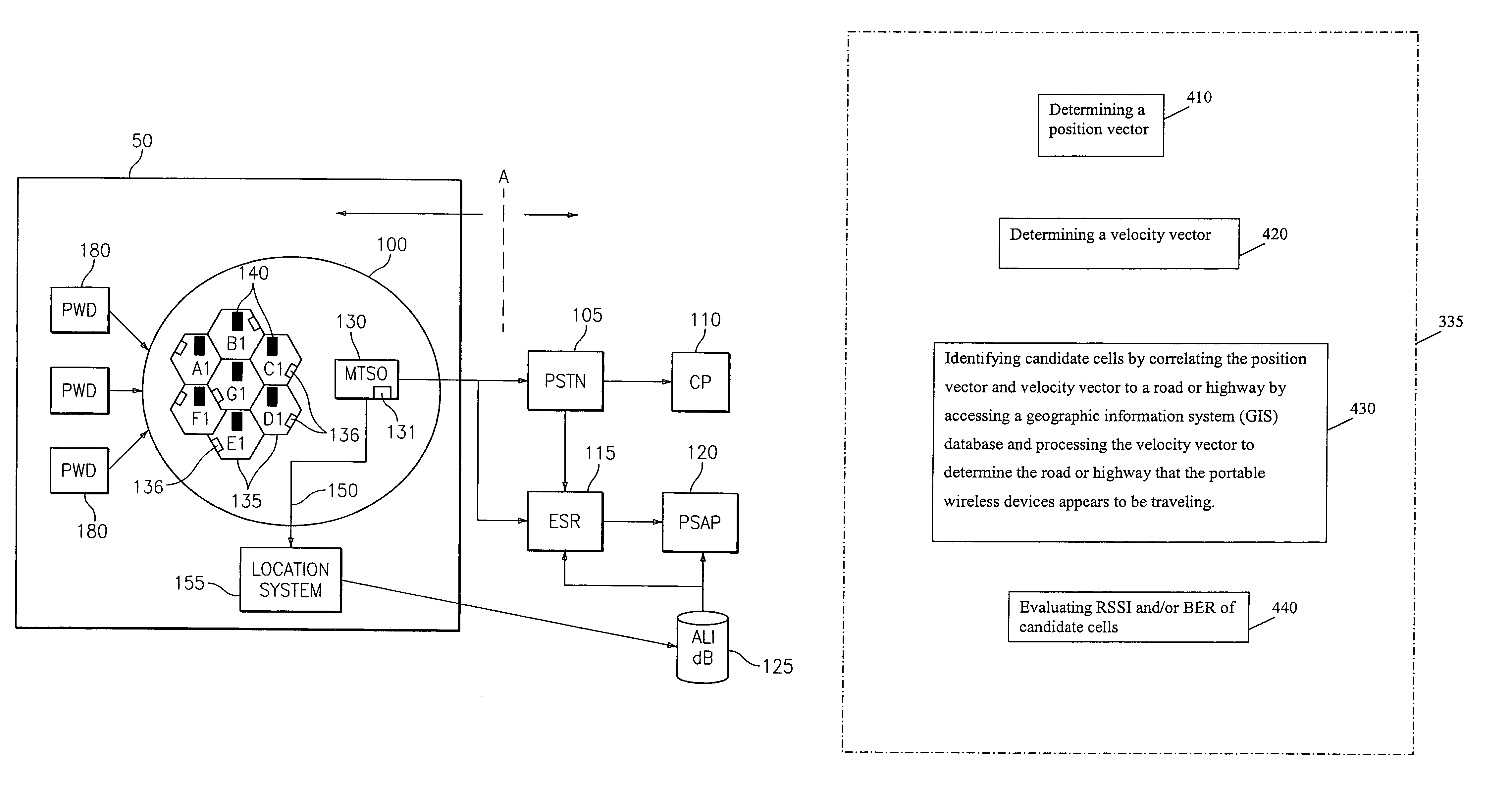
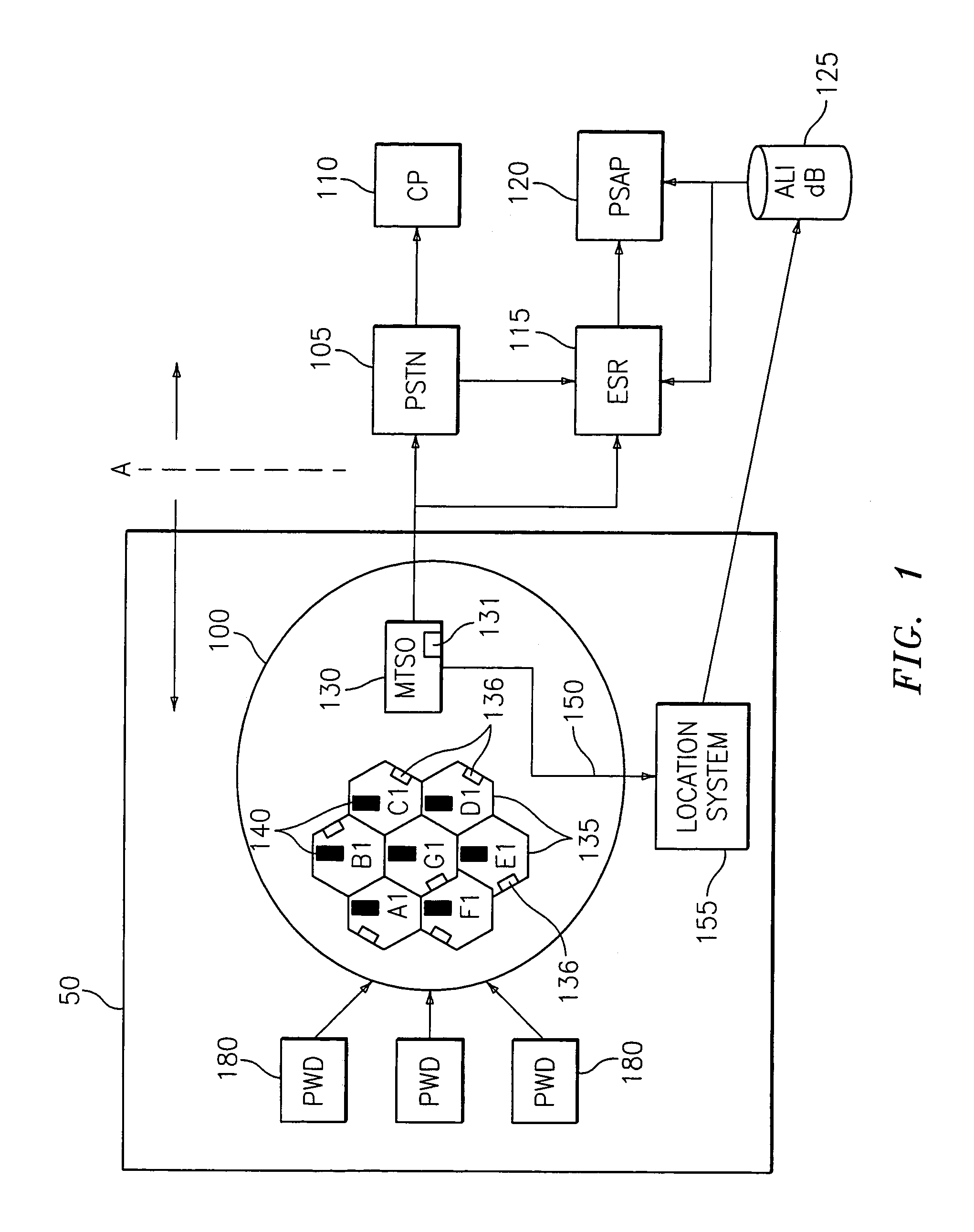
[0035]FIG. 1 is a block diagram, according to an embodiment of the invention, for a system 50 that uses location information for purposes of management and control of a cellular system. System 50 may be part of a larger system that includes an interface to the emergency services infrastructure of the public switched telephone network. The elements to the left of line A in FIG. 1 relate to a cellular system, while those elements to the right of line A relate to the public switched telephone network, sometimes referred to as the Plain Old Telephone System or “POTS.”

[0036]Portable wireless devices 180 interface with cellular system 100 to place phone calls (or to transmit non-voice data) to other portable wireless devices 180 in cellular system 100 or to devices (e.g., land line telephones) in the public switched telephone network (PSTN). The portable wireless devices 180 could be any two-way device that permits the position of the device to be localized using suitable localization tec...


PUM


Abstract

A system and method for controlling operations in a cellular system is disclosed. A serving cell or the mobile telephone switching office (MTSO) determines that a portable wireless device operating in a serving cell needs to be handed off (a “handoff”). The position of the portable wireless device is determined. The position may be determined based on any of a variety of localization techniques, such as time difference of arrival (TDOA), angle of arrival (AOA), location pattern matching (LPM), global positioning system (GPS), or other localization techniques. A target cell is selected based on the position of the portable wireless device. Generally, the target cell is selected as the cell that is closest to the portable wireless device. Factors such as a position vector and/or a velocity vector may be assessed in selecting the target cell. Based on the target cell that is selected, the MTSO assigns the portable wireless device to the target cell and the transmission is handed off to the new cell.

Description

FIELD OF THE INVENTION[0001]The present invention generally relates to communications technology and, more particularly, to channel allocation in cell sites.BACKGROUND OF THE INVENTION[0002]Geographic reuse of frequencies, sometimes called “frequency reuse,” is a distinguishing feature of cellular systems. Because a limited swath of the RF spectrum is available, frequencies are reused in order to provide a cellular system with an acceptable capacity. This is accomplished by breaking up the coverage area into a number of cells, or cell sites, each having a relatively low-powered transmitter. The transmitter has sufficient power to cover the cell site without interfering with other cell channels.[0003]Frequencies can be reused by spacing “same channel” cells sufficiently far apart that the likelihood of interference is minimized. This permits two conversations to occur simultaneously on the same channel without conflict. Frequency reuse may be implemented using an architecture with a ...

Claims


Application Information

Patent Timeline
IPC IPC(8): H04Q7/20H04Q7/00H04W36/32
CPCH04W36/32
Inventor JOHNSON, DEREKHEUBEL, MICHAEL L.
Owner BELLSOUTH INTPROP COR
Why Eureka
Try Eureka