Eureka AIR delivers breakthrough ideas for toughest innovation challenges, trusted by R&D personnel around the world.

Method and apparatus for mounting a fluid containment cylinder

a technology for storing fluids and cylinders, applied in the field of fluid storage, can solve the problems of difficult attachment of pressure vessels to vehicles, poor handling of misalignment, and design problems

Inactive Publication Date: 2006-01-17
HEXAGON TECHNOLOGY AS
View PDF8 Cites 32 Cited by
  • Summary
  • Abstract
  • Description
  • Claims
  • Application Information

AI Technical Summary

Benefits of technology

The present invention provides a unique combination of structures for safely securing a pressure vessel under various conditions. The invention includes a frame with a neck receiving bore and a fastener with a neck receiving end and threaded uprights for securing the assembly. The rotational orientation of the cylinder is fixed using a locating collar. The invention also includes a frame with a spherical inner surface and a retainer for capturing the spherical bearing. The technical effects of the invention include secure mounting of pressure vessels against axial and rotational movement, accommodating misalignment without stressing the neck of the vessel, and ensuring safe and reliable operation of the pressure vessel.

Problems solved by technology

Unfortunately, the rounded shape can make securing such a pressure vessel to the vehicle difficult.
Unfortunately, such designs suffer from a number of drawbacks.
Certain designs handle misalignment poorly, and can place substantial stresses on the neck structure in the event of misalignment.
Certain designs inadequately secure the neck, so that there is an unacceptable risk that the cylinder might work itself free under the right conditions.
Finally, certain designs are such that the cylinder can rotate about the principal axis of the cylinder, thereby placing stress on the connection lines or other attached hardware.

Method used


Image

  • Method and apparatus for mounting a fluid containment cylinder
  • Method and apparatus for mounting a fluid containment cylinder
  • Method and apparatus for mounting a fluid containment cylinder

Examples


second embodiment

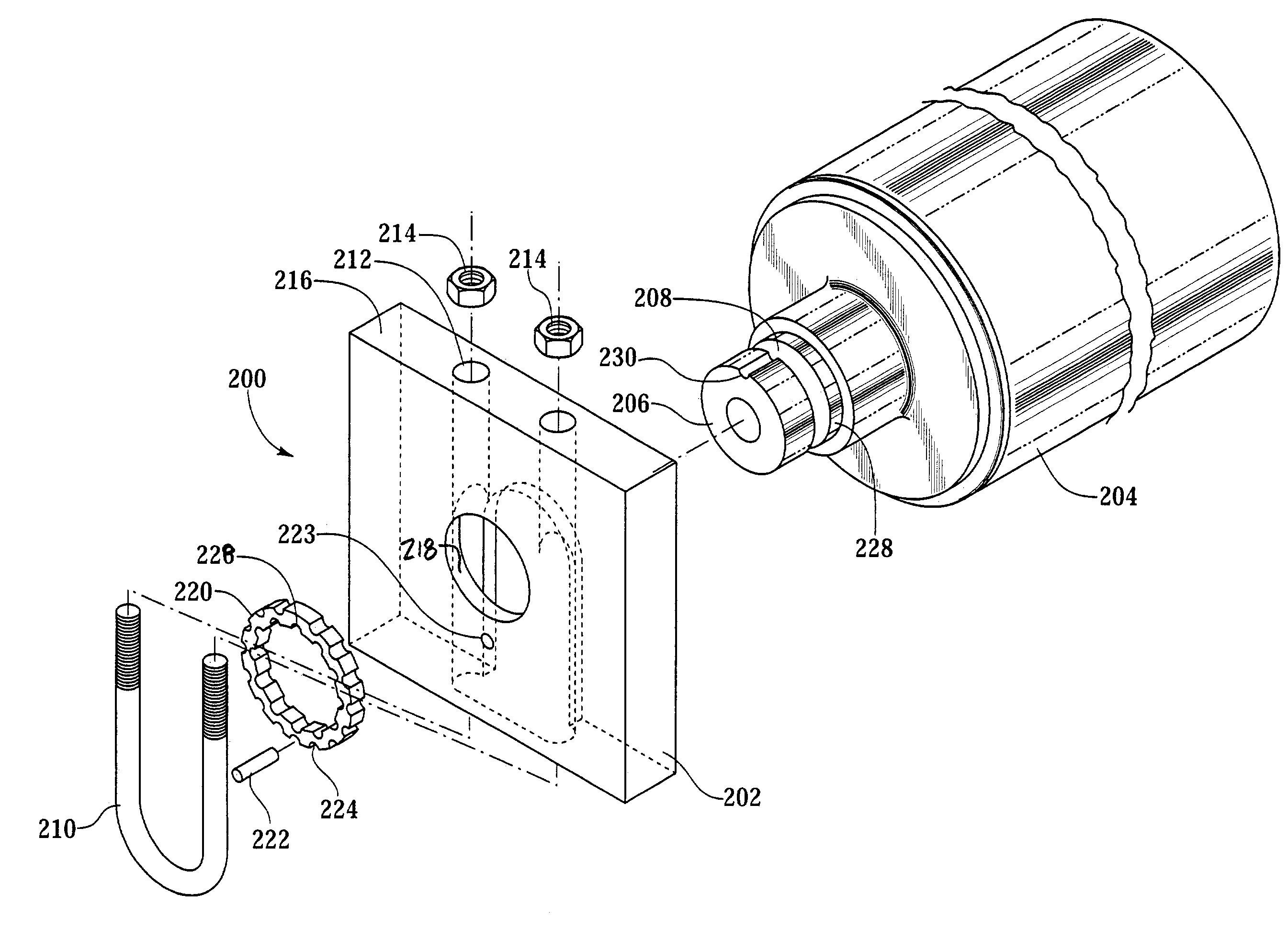
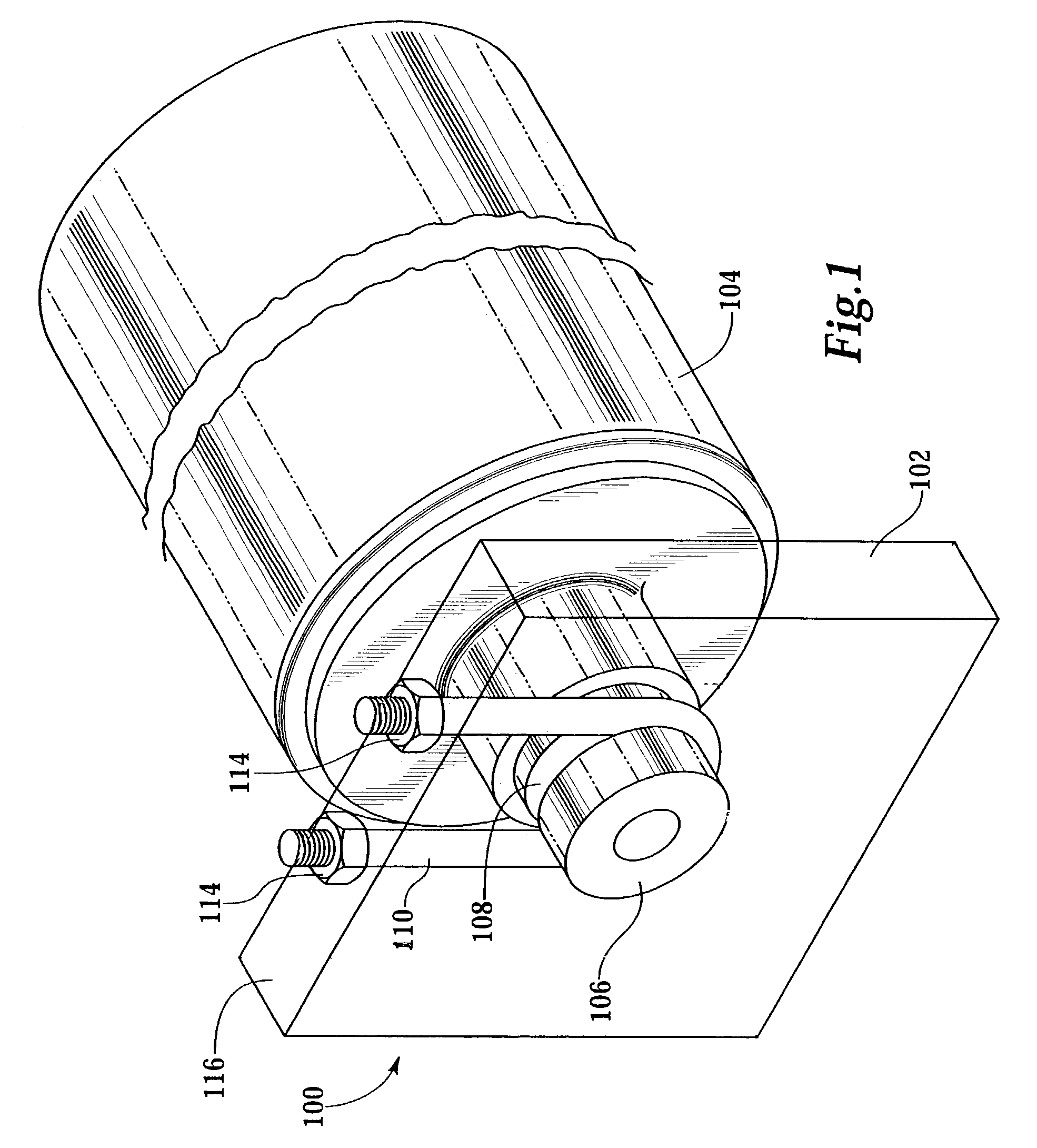
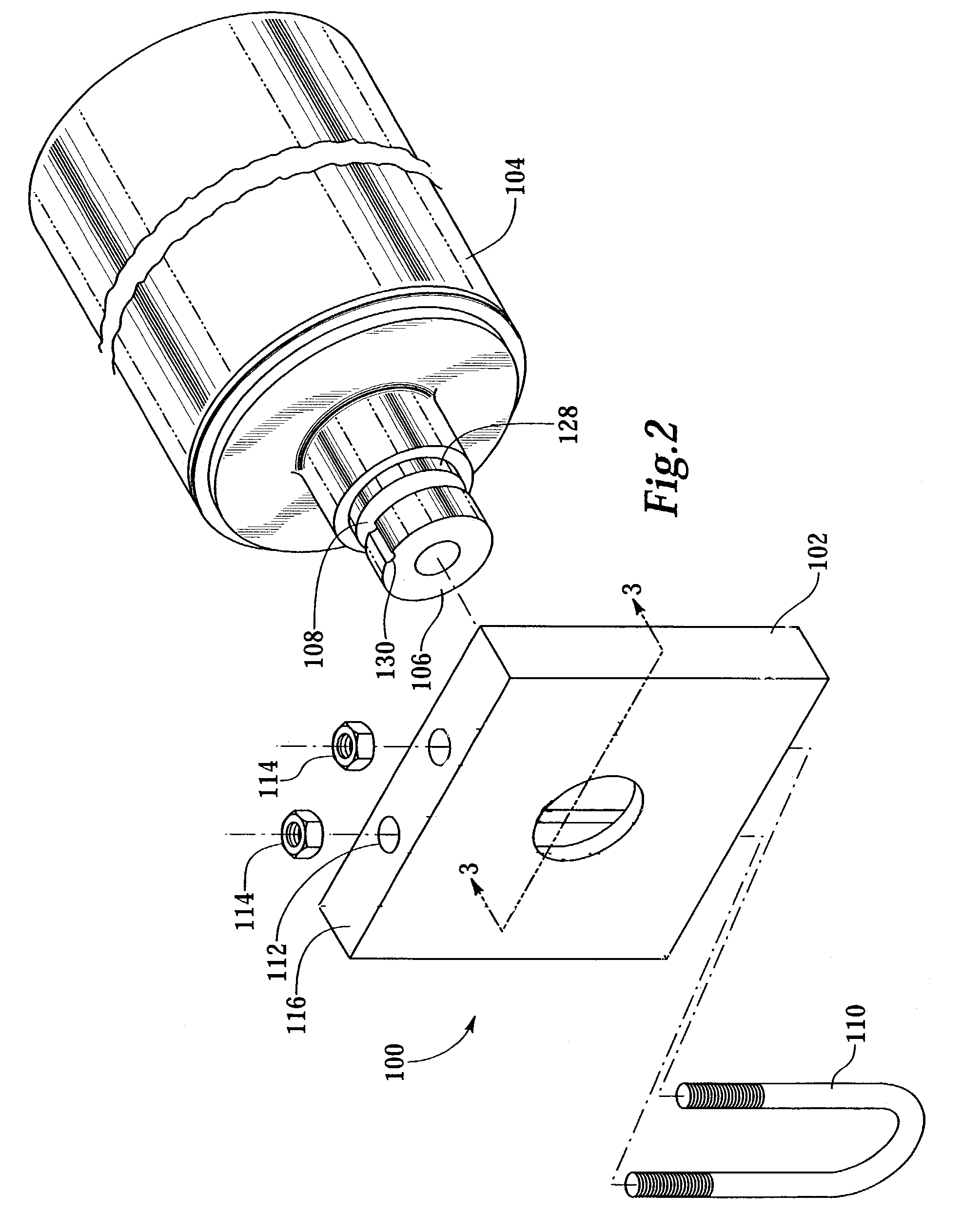
[0031]FIG. 5 depicts an isometric view of a compressed gas cylinder and mount assembly according to the present invention. FIG. 6 depicts an exploded isometric view of the assembly of FIG. 5. As seen in FIGS. 5 and 6, cylinder and mount assembly 200 includes a rigid frame 202 designed to receive a cylinder 204 by the neck 206 of cylinder 204. In this embodiment, the frame 202 captures neck 206 and fixes it in its axial position by registering against an annular groove 208 in the neck 206. The securement is accomplished by a fastener 210, which may be a u-bolt, as shown in FIG. 5. Those of skill in the art will have knowledge of other suitable fasteners, including but not limited to the fasteners specifically described above in connection with fastener 110. In this embodiment, the fastener 210 is held in place by one or more nuts 214 threadably engaged to one or more threaded portions of fastener 210. As with fastener 110, there is nothing within the spirit and scope of the present i...

fourth embodiment

[0041]FIG. 10 depicts an isometric sectional view of a compressed gas cylinder and mount assembly 400 according to the present invention. Cylinder and frame assembly 400 makes use of a cylindrical bearing 410. Cylindrical bearing 410 is disposed around the outer surface of neck 406. The inner surface 422 of cylindrical bearing 410 is shaped and sized to mate with the outer surface of the neck 406.

[0042]In the embodiment shown in FIG. 10, the inner surface 422 is cylindrical, in order to conform to the cylindrical shape of the neck 406. Cylindrical bearing 410 is slidable on neck 406. As assembled, cylindrical bearing 410 seats against a cylindrical inner surface 416 in the frame 402. Similarly, neck 406 has a certain degree of freedom of movement in axial displacement within cylindrical bearing 410, with such axial displacement being bounded on the one end by the shoulder on 422 and at the other end by securement plug 420. With this arrangement, the cylindrical bearing 410 is captur...


PUM


Abstract

Structures for securing a fluid containment cylinder at the neck portion of the cylinder include a mounting frame having a bore disposed therein and a slot disposed orthogonally to the central axis of the bore. The neck of the cylinder passes through the bore and a u-bolt passes through the slot, registering against a shoulder on the neck of the cylinder, thereby securing the cylinder within the block. In other embodiments, the securing structure includes a collar for preventing rotation of the cylinder or for accommodating a certain degree of misalignment of the cylinder with respect to the securement structure.

Description

[0001]This application claims priority to U.S. Provisional Patent Application Ser. No. 60 / 388,911, filed Jun. 14, 2002.BACKGROUND OF THE INVENTION[0002]The present invention relates generally to fluid storage, and specifically to a method and apparatus for mounting a fluid containment vessel.[0003]In many applications, the qualities of lightweight construction and high resistance to fragmentation and corrosion damage are highly desirable characteristics for a pressure vessel. These design criteria have been met for many years by the development of high pressure composite (fiber reinforced resin matrix) containers; for instance, containers fabricated of laminated layers of wound fiberglass filaments or various types of other synthetic filaments which are bonded together by a thermal-setting or thermoplastic resin. An elastomeric or other non-metal resilient liner or bladder often is disposed within the composite shell to seal the vessel and prevent internal fluids from contacting the...

Claims


Application Information

Patent Timeline
Patent Type & Authority Patents(United States)
IPC IPC(8): A47K1/08F17C1/00
CPCF17C1/00F17C2270/0197F17C2201/0119F17C2201/035F17C2201/054F17C2201/056F17C2203/0604F17C2203/0619F17C2205/0103F17C2205/0107F17C2205/0126F17C2205/0305F17C2209/227F17C2221/011F17C2221/014F17C2221/033F17C2221/035F17C2221/08F17C2223/0123F17C2223/036F17C2260/01F17C2270/0186F17C2270/0189F17C2270/0194F17C2201/0104
Inventor EIHUSEN, JOHN A.NEWHOUSE, NORMAN L.
Owner HEXAGON TECHNOLOGY AS
Why Eureka
Eureka Blog
Learn More