Branching unit with reconfigurable terminal connections

a terminal connection and branching unit technology, applied in the direction of power feeding arrangement, line-transmission details, instruments, etc., can solve problems such as potential risks affecting contacts, and achieve the effect of simplifying the branching unit architecture and reducing the number of switching steps

Active Publication Date: 2006-01-17
ALCATEL LUCENT SAS
View PDF8 Cites 12 Cited by
  • Summary
  • Abstract
  • Description
  • Claims
  • Application Information

AI Technical Summary

Benefits of technology

[0029]This particular structure of the sliding contacts has the advantage over relay contacts of being insensitive to current fluctuations and simplifies the architecture of the branching unit, the coils no longer bei

Problems solved by technology

In the prior art, any fortuitous switching at thi

Method used


Image

  • Branching unit with reconfigurable terminal connections
  • Branching unit with reconfigurable terminal connections
  • Branching unit with reconfigurable terminal connections

Examples


Embodiment Construction

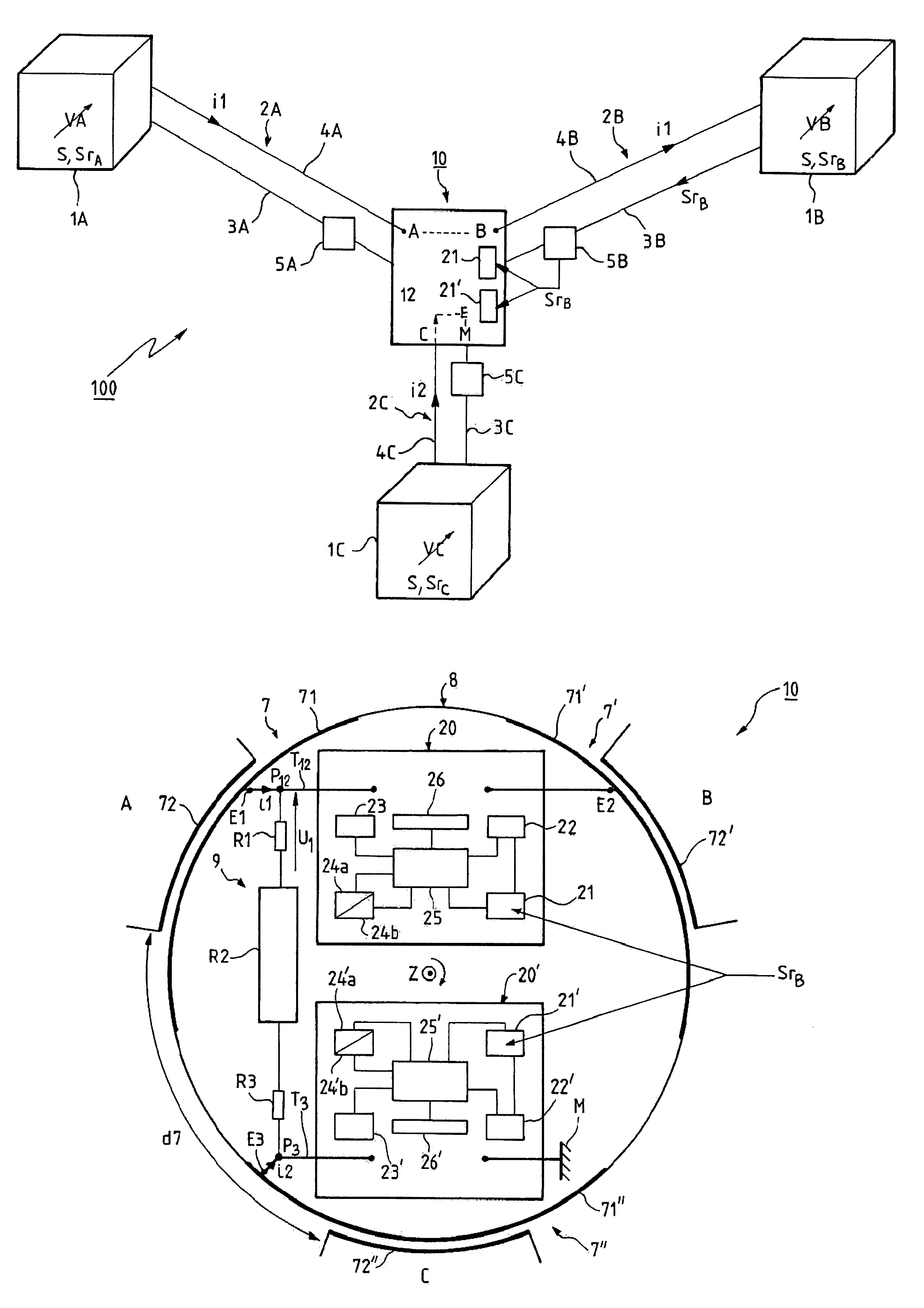
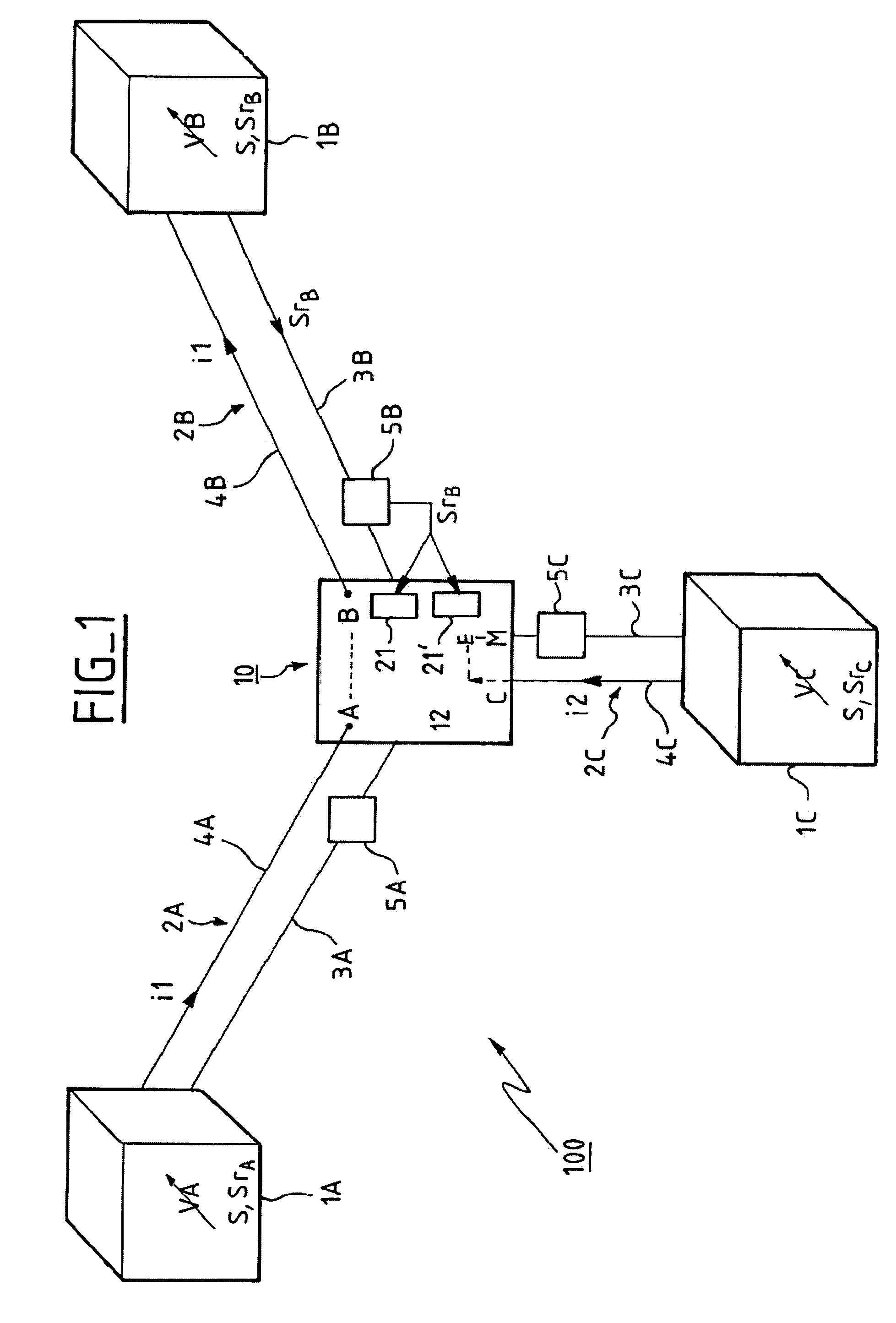
[0051]FIG. 1 shows a submarine telecommunication system 100 integrating a branching unit 10 constituting a preferred embodiment of the invention.

[0052]The submarine telecommunication system 100 comprises three terrestrial optical and electrical power supply terminals 1A, 1B, 1C respectively connected to one end of three cables 2A, 2B, 2C each comprising an optical fiber 3A, 3B, 3C for the propagation of optical signals S and an electrical conductor 4A, 4B, 4C.

[0053]Each electrical conductor 4A, 4B, 4C is further connected to a respective terminal A, B, C of the branching unit 10.

[0054]In a first operating configuration chosen by way of example, the trunk is the connection between the first and second terminals 1A, 1B at respective variable voltages VA, VB respectively equal to +6 kV and −4 kV, for example.

[0055]The first terminal A and the second terminal B are electrically connected, forming a trunk segment (shown in dashed line) at a potential of +3 kV, for example. Thus a trunk c...


PUM


Abstract

A branching unit integrated into a submarine telecommunication system comprising three cables having optical and electrical transmission members comprises three terminals connected to the electrical transmission members of the cables, three input points, and three electrical contacts each between one of the terminals and one of the input points. In an operating configuration, and at a given time, a first terminal and a second terminal are electrically connected together and form a trunk segment adapted to convey a trunk current, and a third terminal is electrically connected to a submarine ground to form a branch segment adapted to convey a branch current. The branching unit carries out reconfiguration by controlling switching of the electrical contacts. A voltage indicating the potential at a point on the trunk segment is measured. Because an optical reconfiguration request is made by means of an optical reconfiguration signal the unit is able to receive and process optical reconfiguration signals. Reconfiguration is validated according to the measured voltage and to the signals received and processed and reconfiguration in accordance with the optical reconfiguration signal is activated only if the absolute value of the potential is below a threshold.

Description

CROSS-REFERENCE TO RELATED APPLICATIONS[0001]This application is based on French Patent Application No. 03 01 585 filed Feb. 11, 2003, the disclosure of which is hereby incorporated by reference thereto in its entirety, and the priority of which is hereby claimed under 35 U.S.C. § 119.BACKGROUND OF THE INVENTION[0002]1. Field of the Invention[0003]The present invention relates to a branching unit for a submarine telecommunication system.[0004]2. Description of the Prior Art[0005]Submarine systems were originally installed to connect two terrestrial optical and electrical power supply terminals (also known as power feed equipments (PFE)) on either side of the Atlantic Ocean, for example. A later improvement comprised three terrestrial optical and electrical power supply terminals connected by a branching unit. Accordingly, in terms of its electrical function, each terminal is connected to one end of an electrical conductor the other end of which is connected to one of the three termi...

Claims


Application Information

Patent Timeline
IPC IPC(8): G02B6/28H04B3/44H04B10/80
CPCH04B3/44
Inventor VERHAEGE, THIERRYCORDIER, ALAINMEJASSON, PATRICK
Owner ALCATEL LUCENT SAS
Why Eureka
Try Eureka