Optical transmission network, optical transmission apparatus, dispersion compensator arrangement calculation apparatus and dispersion compensator arrangement calculation method

a technology of optical transmission network and compensation arrangement, applied in multiplex communication, electromagnetic repeaters, instruments, etc., can solve the problems of increasing the loss at the dispersion compensation, affecting the dispersion of waveforms, and causing wavelength deterioration, so as to reduce the dispersion compensation amount and the number of dispersion compensators

Inactive Publication Date: 2006-01-17
FUJITSU LTD
View PDF9 Cites 7 Cited by
  • Summary
  • Abstract
  • Description
  • Claims
  • Application Information

AI Technical Summary

Benefits of technology

[0080]It is an object of the present invention to provide an optical transmission network, an optical transmission apparatus and a dispersion compensator arrangement calculation apparatus which can reduce the dispersion compensation amount and the number of dispersion compensators.

Problems solved by technology

Generally, since an optical signal is not a signal of a completely single wavelength, it suffers from waveform dispersion by wavelength dispersion (time delay difference depending upon the wavelength) in an optical transmission line.
If this variation is great, then deterioration in wavelength is caused by the wavelength dispersion characteristic of the optical fiber.
That a great dispersion compensation amount is required gives rise to a disadvantage that the loss at the dispersion compensations increases as much, and in order to compensate for the loss, use of an amplifier having a high optical power is required.
Further, that a great number of dispersion compensators are required gives rise to a problem that the an increased investment cost is required.

Method used


Image

  • Optical transmission network, optical transmission apparatus, dispersion compensator arrangement calculation apparatus and dispersion compensator arrangement calculation method
  • Optical transmission network, optical transmission apparatus, dispersion compensator arrangement calculation apparatus and dispersion compensator arrangement calculation method
  • Optical transmission network, optical transmission apparatus, dispersion compensator arrangement calculation apparatus and dispersion compensator arrangement calculation method

Examples


first embodiment

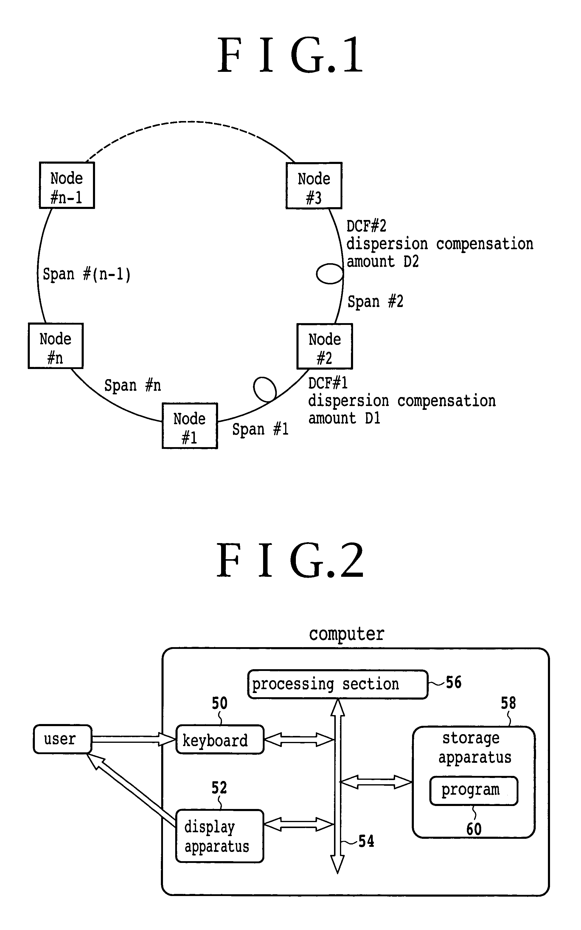
[0124]FIG. 2 is a block diagram of a dispersion compensator arrangement calculation apparatus of an optical transmission network according to an embodiment of the present invention. Referring to FIG. 2, the dispersion compensator arrangement calculation apparatus includes a keyboard 50, a display apparatus 52, a bus 54, a processing section 56 and a storage apparatus 58. The keyboard 50 is an inputting apparatus for inputting design parameters for an optical transmission network and so forth. The design parameters include those of information relating to routes to be used, information relating to spans, information relating to transmission lines, information relating to dispersion compensators and information relating to dispersion tolerances. The information relating to routes to be used is path information of paths of the optical transmission network to be used. The information relating to spans is transmission distances of the spans. The information relating to transmission lines...

second embodiment

[0158]FIG. 6 is a view showing an optical transmission network according to a second embodiment of the present invention. In FIG. 6, for the simplified description, a linear network including totaling four nodes is shown. Here, such prerequisites for the optical network as given below are used:[0159]SMF (single mode fiber);[0160]C-band[0161]maximum wavelength number: 40 waves;[0162]transmission line dispersion coefficient of ch1: 16 ps / nm / km, dispersion compensating fiber dispersion coefficient: −77 ps / nm / km (a dispersion compensator other than a dispersion compensating fiber may be used. In this instance, a dispersion compensation value (ps / nm) is used);[0163]transmission line dispersion coefficient of ch20: 17 ps / nm / km, dispersion compensating fiber dispersion coefficient: −80 ps / nm / km;[0164]transmission line dispersion coefficient of ch40: 18 ps / nm / km, dispersion compensating fiber dispersion coefficient: −83 ps / nm / km;[0165]dispersion tolerance at each node: −100 to +800 [ps / nm] ...

third embodiment

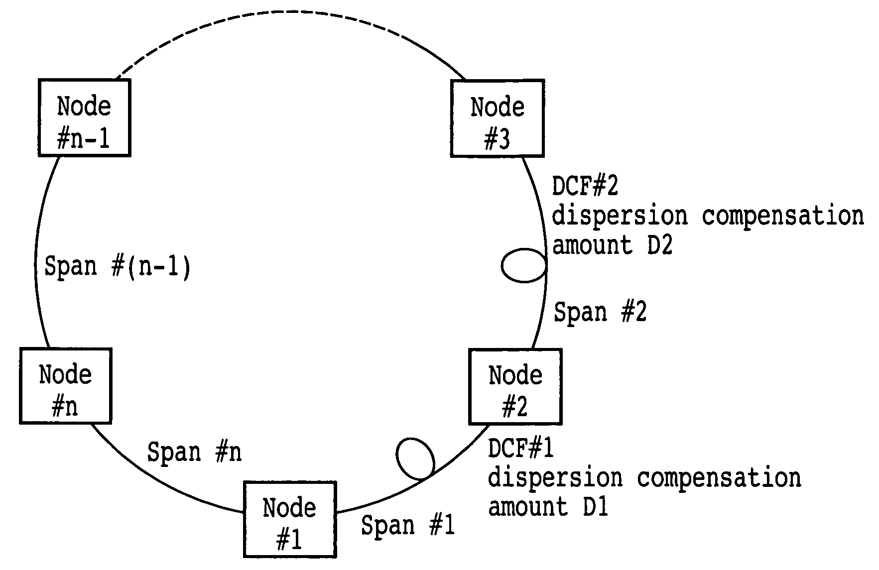
[0184]FIG. 7 is a view showing an optical transmission network according to a third embodiment of the present invention. Where a plurality of spans having a short propagation distance connect successively, or where the dispersion coefficient of the transmission line is low as in the case of a dispersion shift fiber or the like, or else where a part having a negative dispersion such as an optical coupler is used or in a like case, there is the possibility that the accumulated dispersion value may be lower than the lower limit of the dispersion tolerance. The present embodiment is ready also for such a case as just described. In FIG. 7, for the simplified description, a ring network including totaling four nodes is shown. Such prerequisites for parameters of the optical transmission network as given below are used:[0185]DSF (dispersion shift fiber) (while here a DSF is taken as an example of a transmission line having a low transmission light dispersion coefficient, a different fiber ...


PUM


Abstract

An optical transmission network includes a first dispersion compensator arranged in a maximum dispersion span having a maximum dispersion value and searched out from within a maximum dispersion route having a maximum dispersion value from among routes of non-regeneration intervals within which a dispersion value before dispersion compensation does not satisfy an upper limit of a dispersion tolerance, and a second dispersion compensator arranged in a maximum dispersion span having a maximum dispersion value searched out from within a maximum dispersion route having a maximum dispersion value from among the routes when a dispersion compensator is successively arranged until a route of a non-regeneration interval within which a dispersion value of a certain channel does not satisfy the dispersion tolerance does not remain any more based on the dispersion value after the dispersion compensation with respect to the searched out maximum dispersion span. The dispersion compensation amounts of the first and second dispersion compensators are such that, when the dispersion compensation amount of the maximum dispersion span in which the first and second dispersion compensators are arranged is successively increased, the span has a residual dispersion value equal to or higher than a fixed range and the maximum dispersion route which relates to the spans has a residual dispersion value which satisfies the dispersion tolerance or the span has a residual dispersion value which is within the fixed range.

Description

CROSS REFERENCE TO RELATED APPLICATIONS[0001]This is a continuing application, filed under 35 U.S.C. §111(a), of International Application PCT / JP2003 / 005537, filed Apr. 30, 2003.BACKGROUND OF THE INVENTION[0002]1. Field of the Invention[0003]This invention relates to a wavelength division multiplexing optical transmission network having an optical ADM function and including dispersion compensators selected by a dispersion compensation method.[0004]2. Description of the Related Art[0005]Increase of the capacity of a network is proceeding together with the increase of the communication traffic. Recently, not only in backbone networks, but also in metro networks and access networks, construction of an optical transmission network based on the wavelength division multiplexing technique is demanded. In order to construct a network having a higher degree of flexibility, an optical OADM function capable of passing therethrough, adding or dropping light in a unit of a wavelength at a node.[...

Claims


Application Information

Patent Timeline
Patent Type & Authority Patents(United States)
IPC IPC(8): G02B6/28H04B10/2507H04B10/07H04B10/2525H04B10/27H04B10/275H04B10/29H04J14/00H04J14/02
CPCH04B10/25253
Inventor NAKAJIMA, ICHIROTOMOFUJI, HIROAKISAKAMOTO, TAKESHISHIMADA, YUJI
Owner FUJITSU LTD
Why Eureka
Try Eureka