Device for thermal cycling

a technology of thermal cycling and thermal cycling, applied in the field of thermal cycling devices, can solve the problems of unfavorable temperature gradients that may easily be formed within, lack of uniformity, and difficulty in reaction with an accurate

Inactive Publication Date: 2006-01-24
GYROS
View PDF7 Cites 63 Cited by
  • Summary
  • Abstract
  • Description
  • Claims
  • Application Information

AI Technical Summary

Benefits of technology

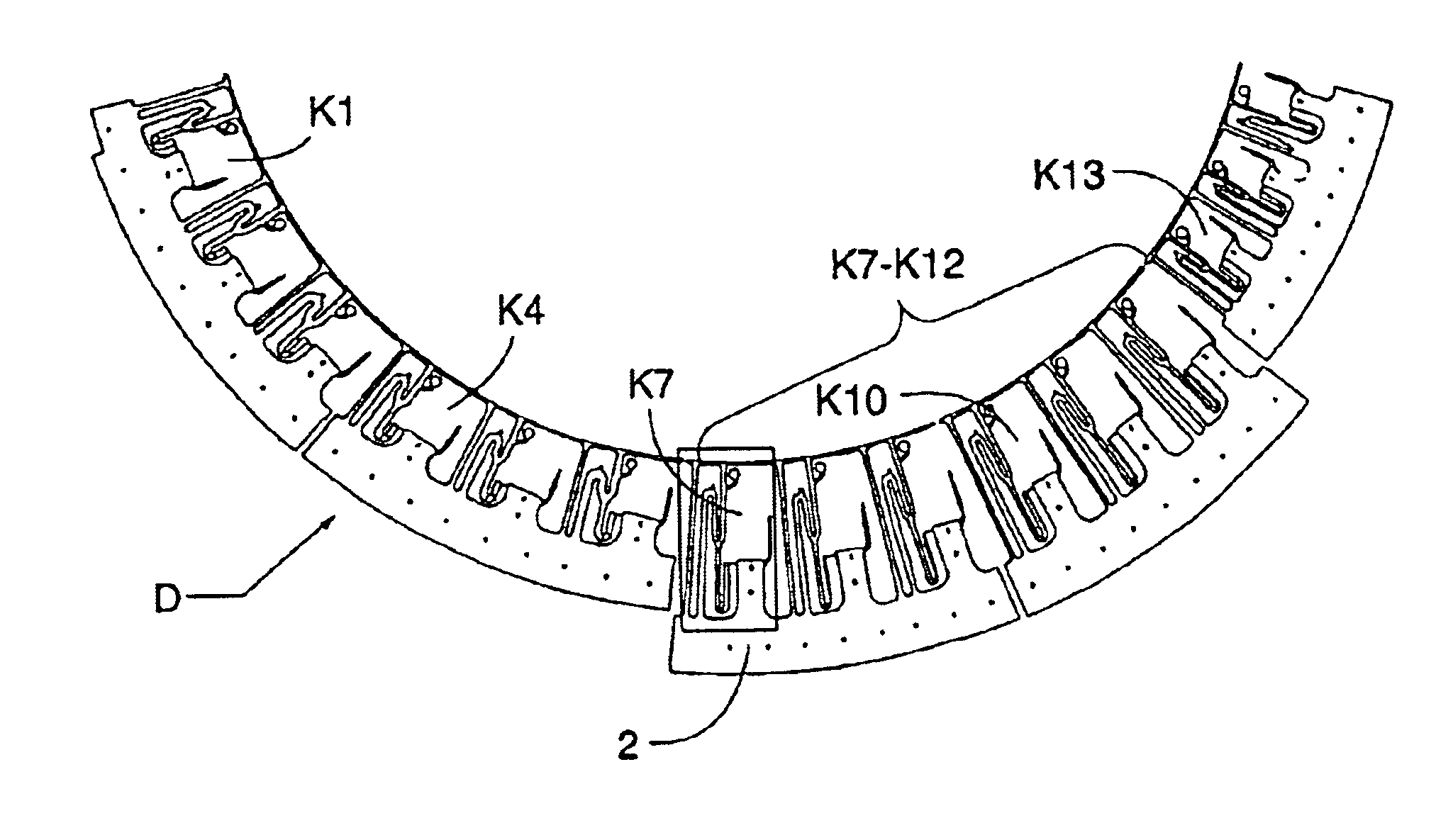
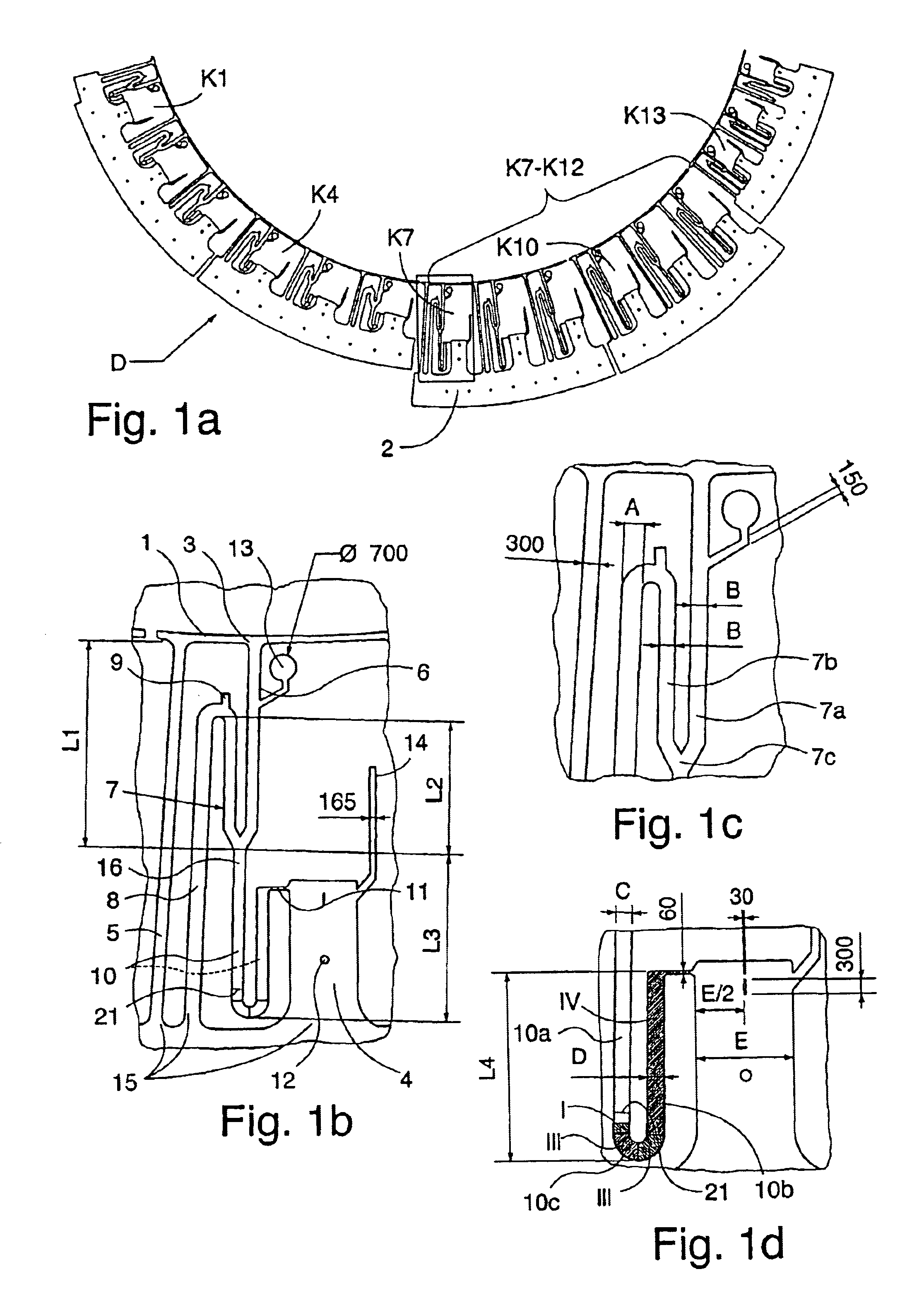
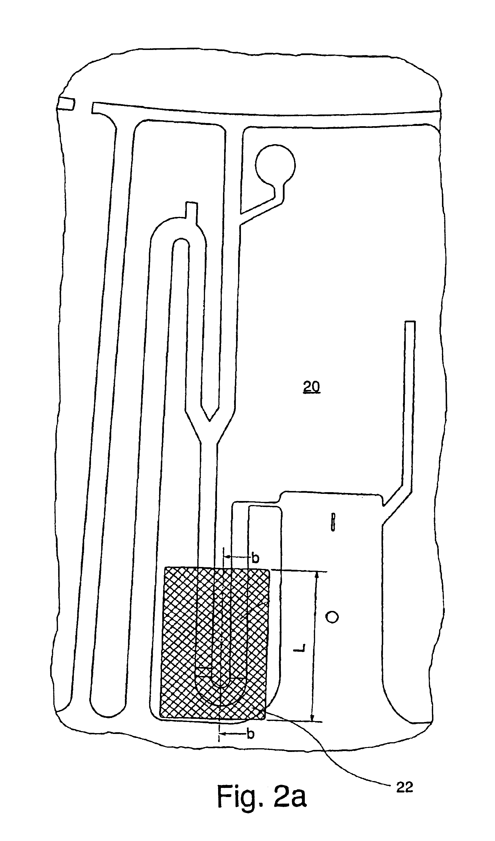
[0011]In view of the shortcomings of prior art systems, it would be desirable to have access to a device for performing thermal cycling, and in particular PCR (Polymerase Chain Reaction) on small sample volumes. The objects of the invention are to provide a method and a device for temperature cycling of a liquid aliquot in a capillary of the dimensions given below, while minimizing the problems discussed above concerning uncontrolled evaporation and / or increase in pressure and / or to accomplish temperature levels that are at a constant level throughout the reaction volume during steps in which the reaction mixture is maintained at an elevated temperature (heating step). The capillary is preferably a part of a microfluidic device as defined below.
[0015]With the device according to the invention it is possible to carry out reactions such as DNA amplification e.g. by PCR in small volumes, which is advantageous in many respects. I.a. the reaction time can be reduced, very many samples can be processed at the same time on a compact device, and very minute volumes of sample can be handled.
[0016]By employing micro channels in the form of a U configuration to define the reactor volume according to an embodiment, another advantage is achieved, namely, it becomes possible to transfer the product of the PCR to further processing steps downstream of the reactor. This has not been possible in the known systems, where the PCR chamber has been the final processing step.

Problems solved by technology

There is also a problem with evaporation when heating small aliquots of liquids within micro channel structures.
Due to the poor thermal conductivity, unfavorable temperature gradients may easily be formed within the selected area when this latter type of materials is used.
For many chemical and biochemical reactions such lack of uniformity can be detrimental to the result, and indeed render the reaction difficult to carry out with an accurate result.
Such temperature variations are often detrimental to the outcome of a reaction and must be avoided.

Method used


Image

  • Device for thermal cycling
  • Device for thermal cycling
  • Device for thermal cycling

Examples


example

[0093]A micro channel structure having a U configuration in a rotatable polycarbonate disc is used. The disc is prepared by fusing a polycarbonate film over the micro channel structures and painting the bottom side with a black pattern. The CD is spun and the black pattern is exposed to visible light from three150 W halogen lamps. The power of the lamps is varied using computer control (software LabView). The surface temperature is measured using an infrared camera.

[0094]A PCR mix is designed to generate a 160 bp product, the composition being given below.

[0095]

FinalComponentconc. / amountPCR buffer (AP Biotech)x1Ficoll 400 (AP Biotech)10%Cresol Red0.2 mg / mldNTPs (AP Biotech)200 μMPrimers (RIT 29 and M13 Universal)*15 pmolAmpliTaq (PEBiosystems)1 UpUC19 Template (AP Biotech)250 ngTotal volume50 μl*RIT 29:5′-Biotin-GCT TCC GGC TCG TAT GTT GTG TGM13 Universal:5′-Cy5-CGA CGT TGT AAA ACG ACG GCC AGT

approximately 0,5 μl of the mix is introduced into the micro channel structure on the disc ...


PUM

PropertyMeasurementUnit
temperatureaaaaaaaaaa
widthaaaaaaaaaa
widthaaaaaaaaaa

Abstract

An apparatus for performing temperature cycling, comprising a micro channel reactor structure (46, 48, 50), and having a heating structure (b1, b2, B1, B2) defining a desired temperature profile. A preferred embodiment of a heating element structure comprises a pattern of areas of a material capable of providing heat when energized, disposed over said micro channel reactor structure.

Description

[0001]The present invention relates to a device for the controlled thermal cycling of reactions, in particular in small channels that are present within a substrate. In particular the invention relates to a micro channel PCR reactor.BACKGROUND OF THE INVENTION[0002]There is a trend in the chemical and biochemical sciences towards miniaturization of systems for performing analytical tests and for carrying out synthetic reactions, where large numbers of reactions must be performed. For example in screening for new drugs as many as 100000 different compounds need to be tested for specificity by reacting with suitable reagents.[0003]Another field is polynucleotide amplification, which has become a powerful tool in biochemical research and analysis, and the techniques therefor have been developed for numerous applications. One important development is the miniaturization of devices for this purpose, in order to be able to handle extremely small quantities of samples, and also in order to...

Claims


Application Information

Patent Timeline
Patent Type & Authority Patents(United States)
IPC IPC(8): A47J31/00B01J19/00G01N37/00B01L7/00C12M1/00C12M1/02
CPCB01L7/54B01L7/52
Inventor KYLBERG, GUNNARSALVEN, OWEANDERSSON, PER
Owner GYROS
Why Eureka
Try Eureka