[0005]In a
piston pump for providing high-pressure fuel in a common-rail fuel injection
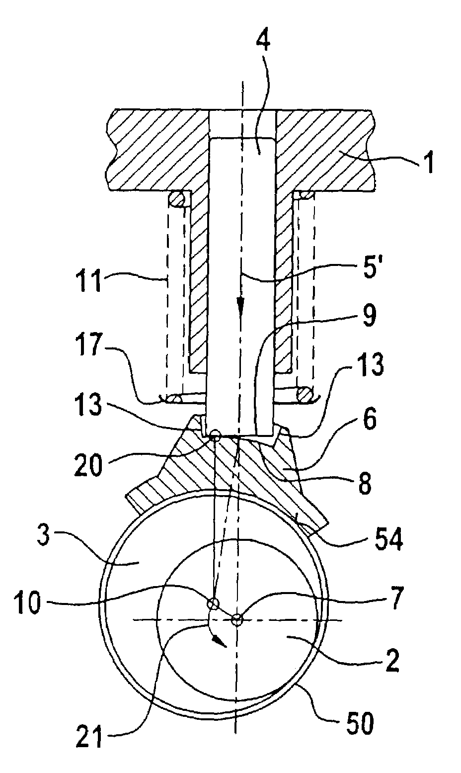
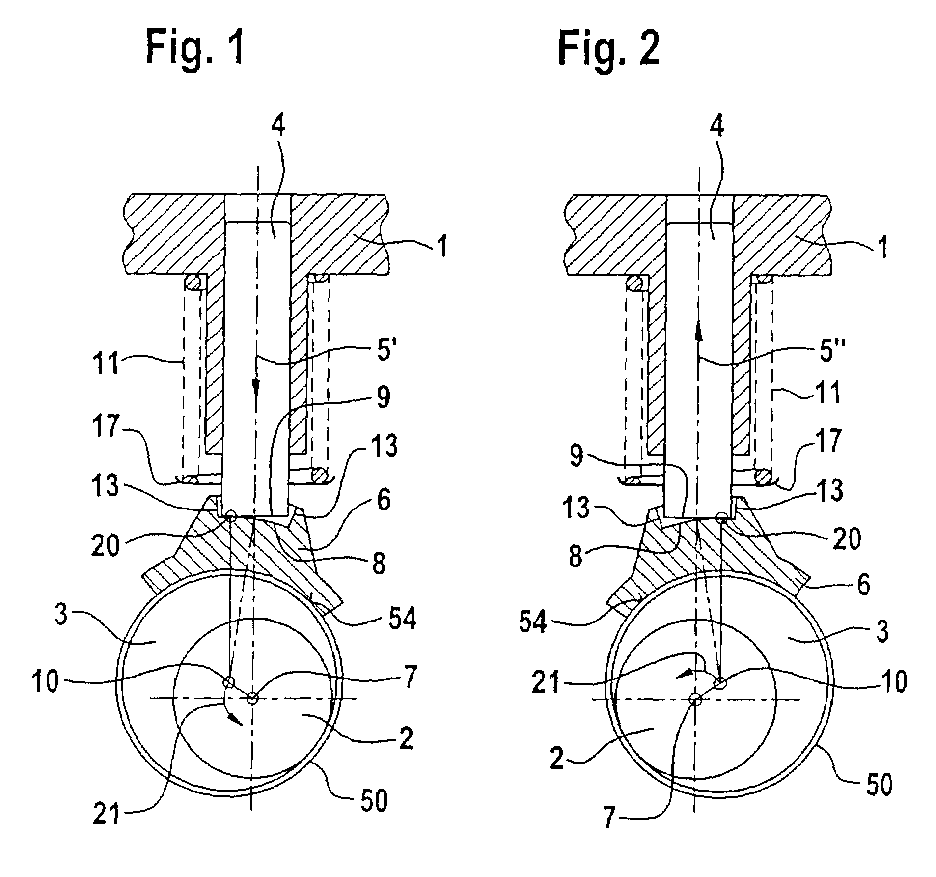
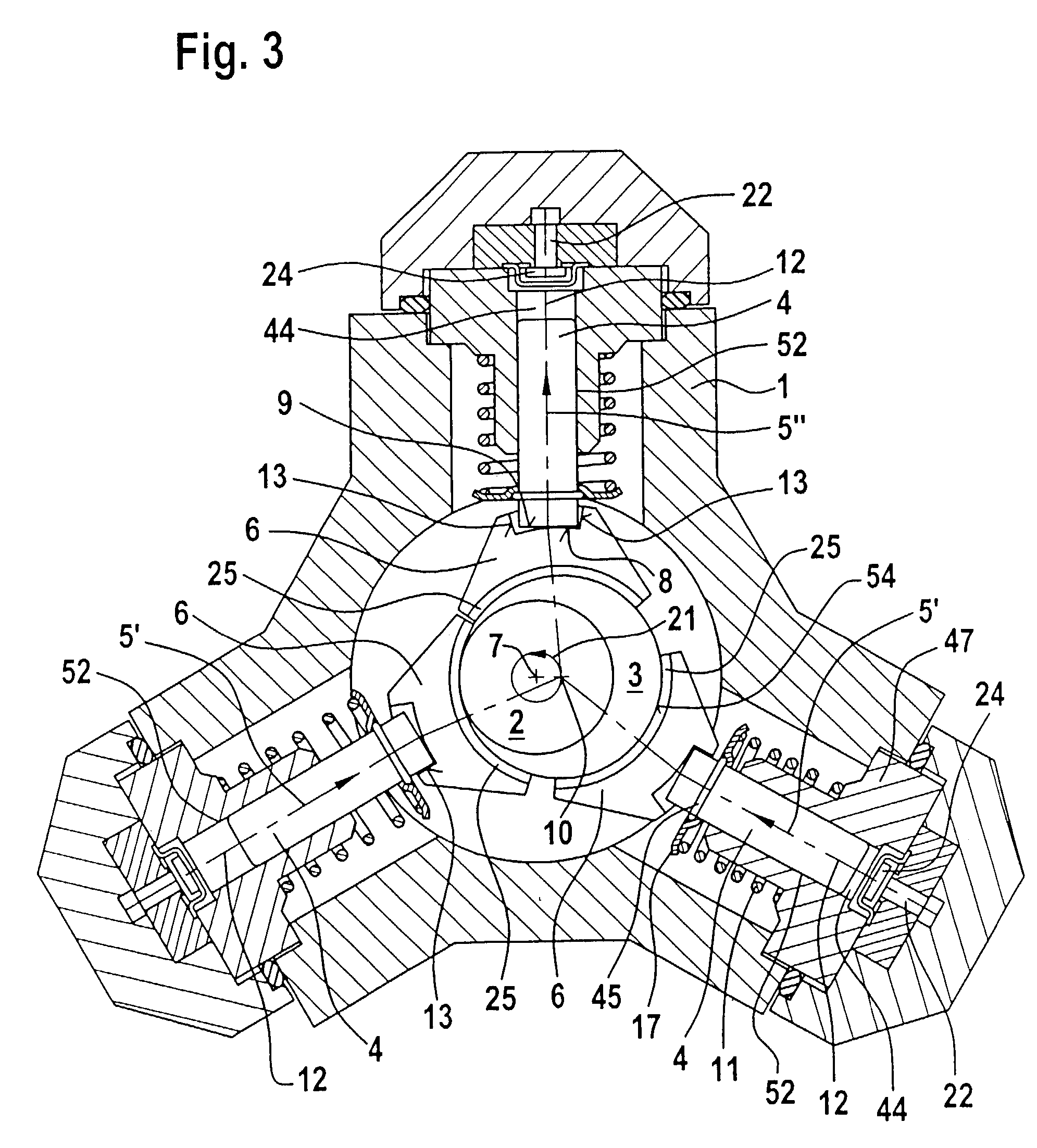
system including a camshaft (2), which is mounted rotatably in a pump housing (1) and which has at least one eccentric cam 93) for operating a pump piston (4, 14) in an approximately radial direction with respect to the camshaft (2), in order to reduce the wear of the
piston pump, a piston-rod element (6, 16, 26, 36, 46) is arranged between each pump piston (4, 14) and the eccentric cam (3) so as to transmit the
stroke movement (5) and the force from the eccentric cam of the camshaft (2) to the pump piston (4, 14) by a rolling movement thereby reducing friction and wear.
[0007]The piston-rod element is expediently in contact on one contact surface with the contact surface of the pump piston, with at least one of the contact surfaces being of convex design. This enables a rolling movement to be obtained between the pump piston and
piston rod element, with the result that no sliding friction and therefore virtually no wear occurs between the pump piston and
piston rod element. By means of the use of the
crank-mechanism principle in conjunction with the rolling
coupling and transmission of force from the piston-rod element to the pump piston, the sliding friction, which occurs in the prior art, between the polygon ring and piston-end disc is thus avoided, in which case the
surface pressure which occurs in the contact surface area between the piston-rod element and the pump piston clearly remains below the permissible
limit value because of the large diameters which can be realized for the radii of curvature of the contact partners.
[0008]It may be advantageous for one of the contact surfaces to be concave, with the
radius of the concave contact surface being greater than the
radius of the convex contact surface. The concave and convex contact surfaces roll on each other. The difference between the radii of curvature is as small as possible so as to minimize the
surface pressure. However, it may also be advantageous for both contact surfaces to be convex. One contact surface, in particular the contact surface of the pump piston, is expediently planar. The planar contact surface is expediently arranged perpendicularly with respect to the longitudinal axis of the pump piston. However, it may be advantageous, particularly in order to compensate for tangentially acting dynamic forces, for the planar contact surface of the pump piston to be inclined relative to the longitudinal axis of the pump piston.
[0011]In order to provide for a compact design a plurality of piston-rod elements may be distributed around the circumference of the eccentric cam. In order to avoid the possibility of the piston-rod elements becoming detached in the radial direction from the eccentric cam during the down-
stroke, fingers may protrude from each piston-rod element in the circumferential direction, which fingers engage adjacent piston-rod element with a small radial spacing. The fingers expediently extend from each piston-rod element in the circumferential direction towards both sides. Since there is always only one piston-rod element in a down-stroke mode, the adjacent piston-rod elements, which are pressed in the upstroke against the eccentric cam by the pump piston, can hold the piston-rod element, which is in the upstroke, in place. However, it may also be advantageous for the pump piston to be pressed against the piston-rod element by means of a spring. In this case, the fingers serve as a safety device in the event of a spring breakage. In order to avoid that the pump piston does not follow the piston-rod element in the down-stroke particularly if the spring breaks, provision is made for the pump piston to be held on the piston-rod element in a form-fitting manner, in particular by means of a clip. If the pump piston and
piston rod elements are connected in a form-fitting manner, a spring does not have to be provided.
[0014]In order to reduce the
surface pressure, the piston-rod element may be of multi-part design, the individual segments being arranged in the direction of the piston longitudinal axis and being moveable relative to one another on contact surfaces, and, in particular, the radii of curvature of the contact surfaces increasing outwards in the radial direction. As a result, a convexly curved contact surface rolls in each case on a concavely curved contact surface. The
effective radius decisive for the Hertzian stress increases herein as the difference between the radii decreases. The arrangement of a plurality of parts of a piston-rod element thus enables the Hertzian stress to be reduced.
[0015]In order to reduce wear, the piston-rod element may have an insert made of wear-resistant material, in particular of anti-friction bearing steel or of
ceramic, in the region of the contact surface. In order to reduce the friction and to improve the emergency running properties, a bearing-shell segment may be arranged on the piston-rod element between the piston-rod element and the eccentric cam, the said bearing-shell segment being, in particular, PTFE-coated. The bearing-shell segment is expediently soldered onto the piston-rod element, in particular with soft solder or with low-melting, silver-containing solder. In particular, the bearing-shell segment is fastened in a form-fitting manner, advantageously by bending it over and / or clipping it on. However, it may also be expedient for a bearing sleeve particularly one, which is coated with PTFE, to be arranged on the circumference of the eccentric cam.

