Open cavity extrusion dies

a technology of extrusion dies and cavities, which is applied in the field of open cavity extrusion dies, can solve the problems of die design, significant higher die fabrication cost, and clogged passages in the dies

Inactive Publication Date: 2006-01-31
CORNING INC
View PDF17 Cites 17 Cited by
  • Summary
  • Abstract
  • Description
  • Claims
  • Application Information

AI Technical Summary

Benefits of technology

[0022]Each of the feed streams thus formed is next conveyed directly and linearly along the feed channels (i.e., without angled or stepwise lateral flow translations) toward a plurality of slot base ends opening into a crisscrossing array of discharge slots disposed in a honeycomb forming section of the die. The absence of angular or lateral flow translations insures minimal channel-induced pressure drops within the feed streams.
[0023]As the feed streams exit the feed channels, each feed stream is next divided by flow over and past a...

Problems solved by technology

These surfaces tend to increase flow impedance and create flow stagnation points within the dies, the latter acting as sources for agglomerate formation that can lead to clogged passages within the dies and/or regions of batch inhomogeneity caused by the preferential collection of batch constituents such as water, plasticizers, and lubricants at the stagnation points.
Smoother flow profiles are provided in laminated dies such as those disclosed in U.S. Pat. No. 6,558,151 and bonded pin dies such as disclosed in published Japanese Patent Application No. 62-236,710, but at a significantly higher die fabrication cost.
Also costly are die designs such as di...

Method used


Image

  • Open cavity extrusion dies
  • Open cavity extrusion dies
  • Open cavity extrusion dies

Examples


example 1

Honeycomb Die Construction

[0051]A 5 cm-thick billet of solid tool steel is selected for use as a cavity plate in a two-part honeycomb extrusion die. In order to provide extrudate feed channels in the plate, an array of pilot holes of approximately 3 mm diameter is first drilled through the billet using mechanical drilling. Thereafter the array of pilot holes is converted to a close-packed array of feed channels of rounded polygonal (square) cross-section by inserting a wire through each pilot hole and routing out each feed channel by wire electrical discharge machining (EDM). The feed channels thus provided are rounded square holes approximately 4.285 mm on a side at a center-to-center channel spacing of about 5 mm.

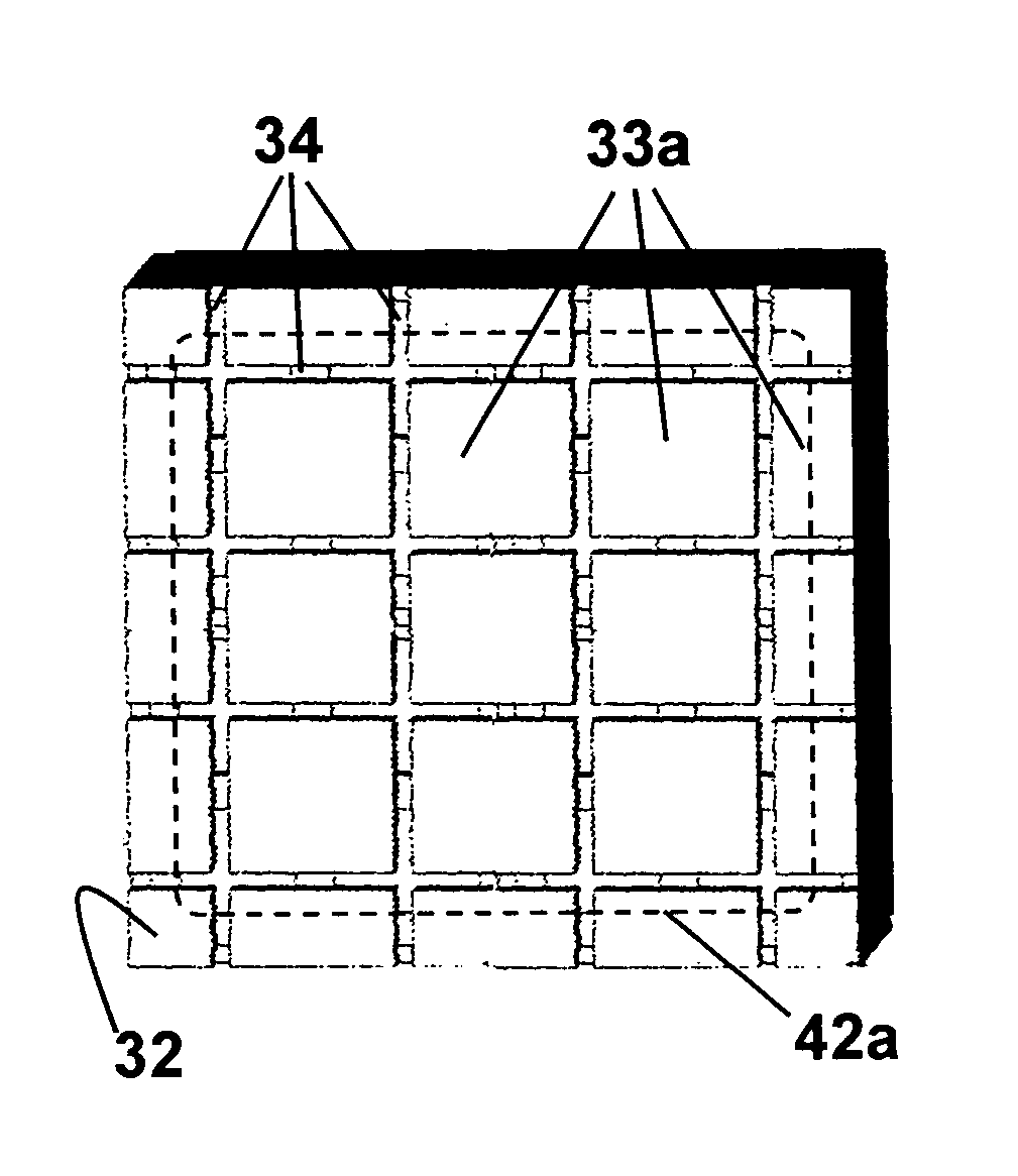
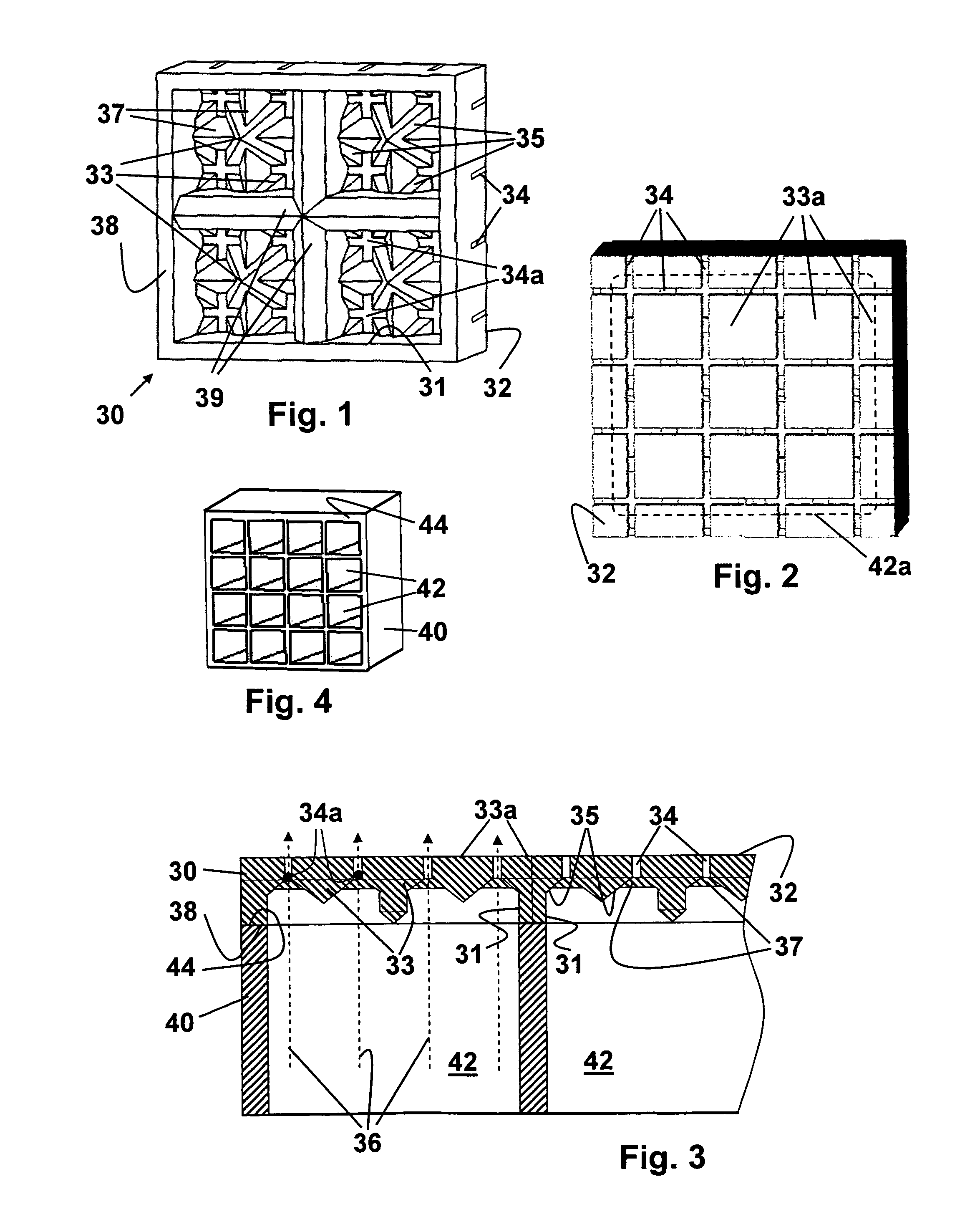
[0052]A 2.5 cm-thick billet of tool steel is selected for use to fabricate a honeycomb forming plate for the two-part die. Extrudate transfer openings are first formed in one surface of this plate by plunge electrical discharge machining (EDM). An EDM electrode suitable f...


PUM

PropertyMeasurementUnit
Fractionaaaaaaaaaa
Sizeaaaaaaaaaa
Shapeaaaaaaaaaa

Abstract

Honeycomb structures are formed at reduced extrusion pressures and high extrusion rates via extrusion through open cavity honeycomb extrusion dies incorporating large, closely spaced feed channels delivering extrudable material to die honeycomb forming sections incorporating extrudate distribution means in the form of inverted conical or pyramidal flow dividers incorporating inclined flow-guiding surfaces that guide the extrudate into the base ends of plural discharge slot intersections and/or slot segments in direct line with the feed channels.

Description

BACKGROUND OF THE INVENTION[0001]The present invention relates to methods and apparatus for forming extrudable materials such as plasticized powder batches or pastes into complex structures, such as honeycombs, by the process of extrusion. More particularly, the invention relates to improvements in extrusion apparatus and extrusion methods that enable the production of cellular structures such as extruded honeycombs from extrudates such as plasticized ceramic or metal powder batches at higher extrusion rates and lower extruder pressures.[0002]The manufacture of inorganic honeycomb structures from plasticized powder batches comprising inorganic powders dispersed in appropriate binders is well known. U.S. Pat. Nos. 3,790,654, 3,885,977, and 3,905,743 describe extrusion dies, processes, and compositions for such manufacture, while U.S. Pat. Nos. 4,992,233 and 5,011,529 describe honeycombs of similar cellular structure extruded from batches incorporating metal powders.[0003]While contin...

Claims


Application Information

Patent Timeline
IPC IPC(8): B29C47/12B29C48/30B29C48/11B29C48/12
CPCB23H9/00B29C47/0028B29C47/12B28B3/269B23H2200/30B29L2031/60B29C48/11B29C48/12
Inventor STEPHENS, II, ALAN T.
Owner CORNING INC
Why Eureka
Try Eureka