Filter element

a filter element and filter element technology, applied in the field of filter elements, can solve the problems of filter element loss, most of the thermal energy obtained, filter element loss, etc., and achieve the effect of reducing convection heat loss and small movemen

Inactive Publication Date: 2006-01-31
RYPOS
View PDF16 Cites 35 Cited by
  • Summary
  • Abstract
  • Description
  • Claims
  • Application Information

AI Technical Summary

Benefits of technology

[0050]An identical effect is obtained when the edge of the pleated metal fiber fleece is mounted in a slot in the thermally and electrically insulating side of a flank. As said, a small void space is provided underneath the edge, to allow small movements. The slot fits that good to the edge at the surface to the pleated metal fiber fleece, that under normal circumstances, no gas can bypass the metal fiber fleece via the sides of the edge and these voids. In case there is a small gap between the side of the edge and the slot, soot will be trapped and retained in these gaps. When the filter is regenerated, the soot will not be heated enough in order to incinerate. So the bypass of gas through the gaps is hindered after the gaps are filled with soot, due to such bypass. The filter seals itself.
[0051]Filter elements as subjects of the invention are used to provide filter units. Several filter elements may be combined, e.g. stacked one on top of the other. To avoid thermal losses, the different filter elements are separated from each other by a thermally insulating layer, e.g. a thermally insulating and thermal resistant layer of textile, e.g. a woven SiO2-fabric.
[0052]Filter elements as subject of the invention may be used to filter hot gases, such an exhaust gases from diesel internal combustion engines. Several filter elements or filter units comprising filter elements as subject of the invention may be used in parallel, e.g. to be able to regenerate at least one filter element, through which no gas flows, so reducing convection heat losses, while the other filter elements continue to filter the gas stream. They may be mounted in series connection, to filter the gas stream in different steps, e.g. for different particle sizes.

Problems solved by technology

The presently known filter elements, suitable for electrical regeneration, have the disadvantage that most of the thermal energy, obtained by Joule effects out of electrical energy and used to heat the filter element, is lost due to thermal losses.

Method used


Image

  • Filter element
  • Filter element
  • Filter element

Examples


Embodiment Construction

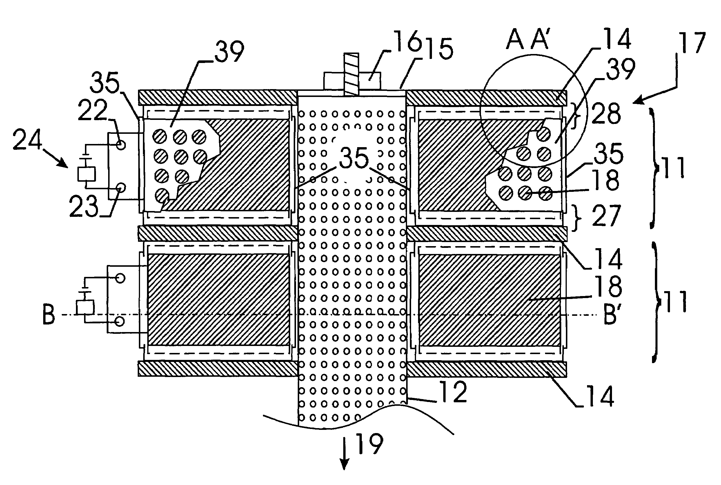
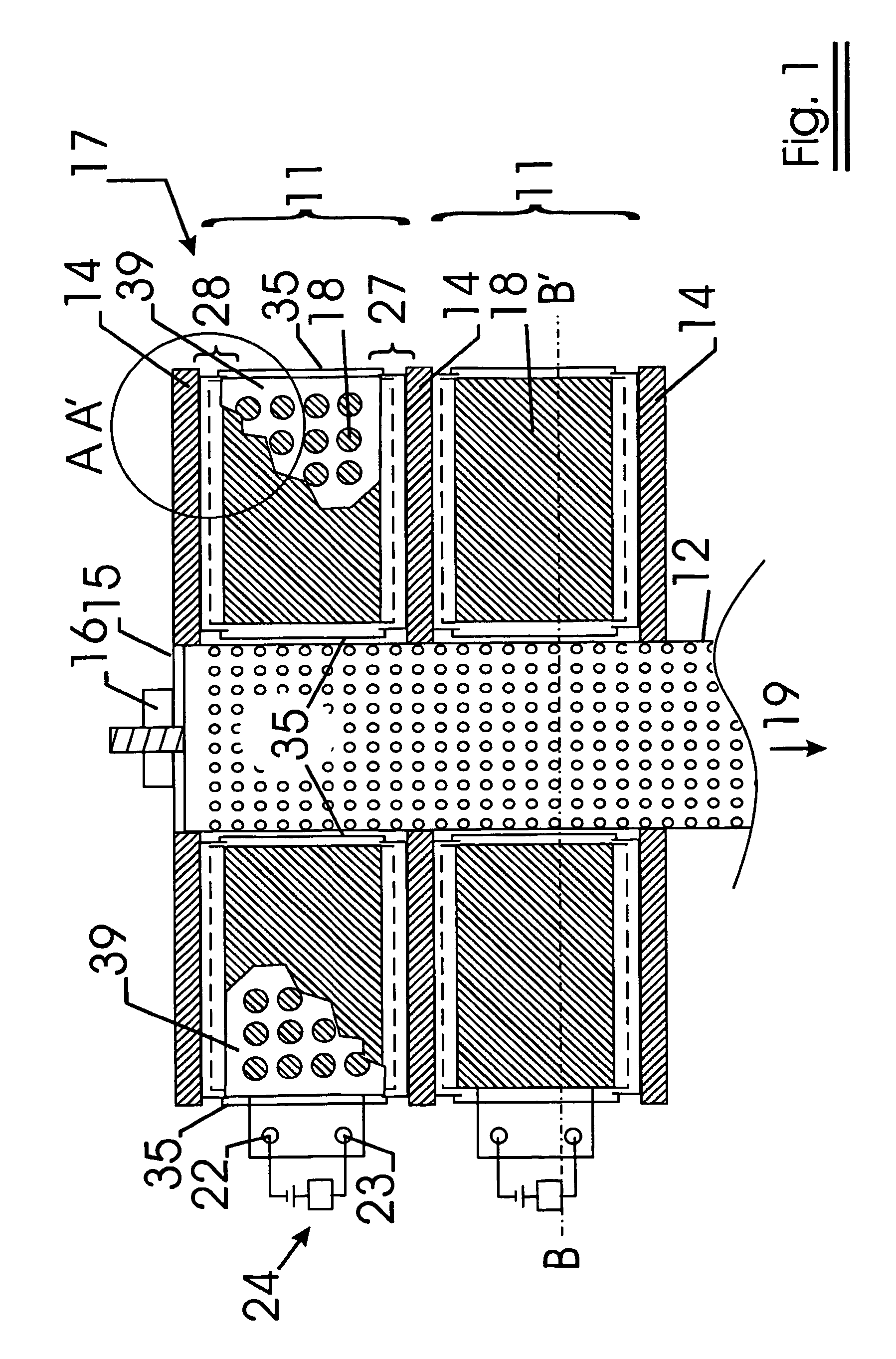
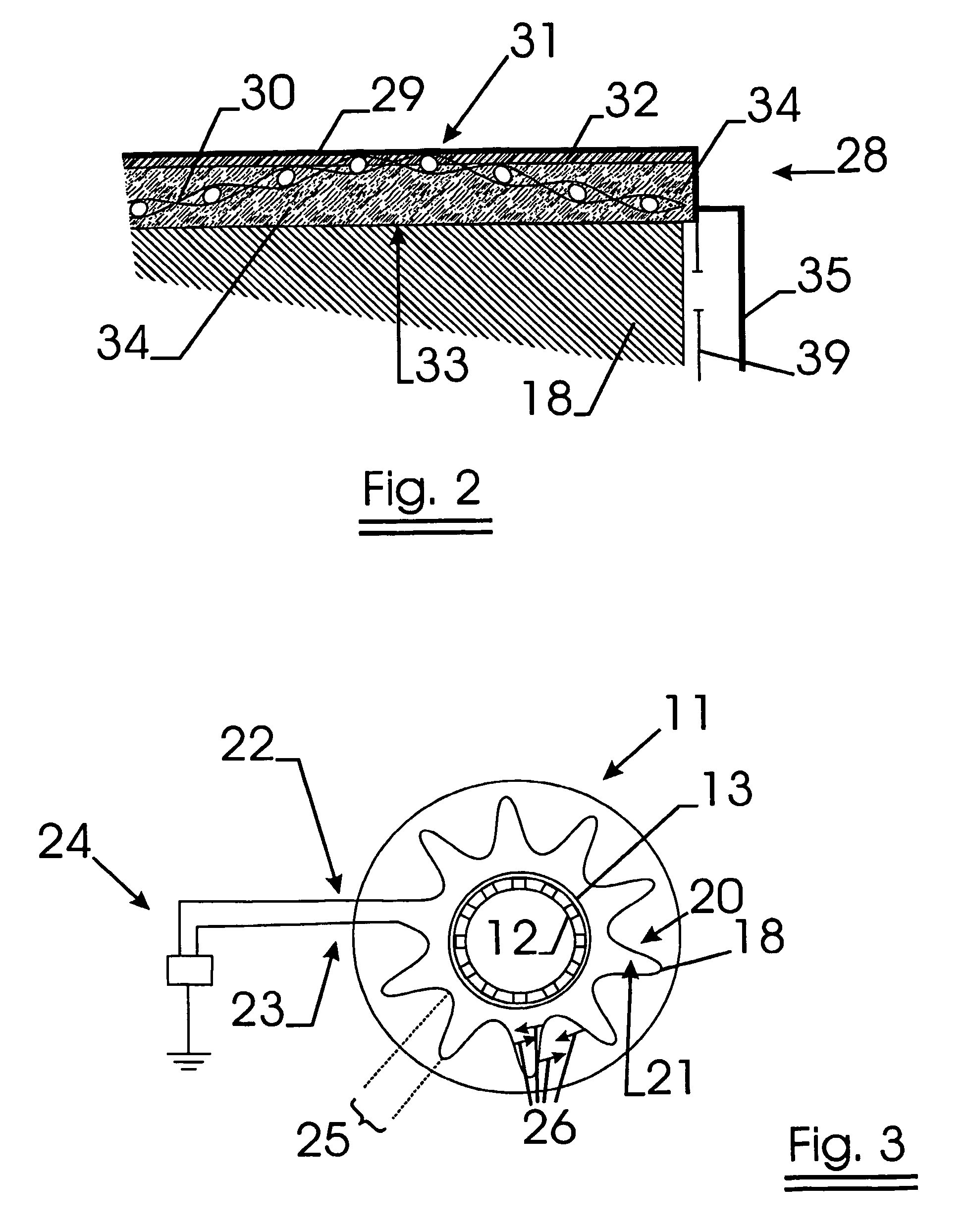
[0062]A preferred filter unit as subject of the invention is shown in FIGS. 1, 2 and 3.

[0063]The filter unit comprises a number of filter elements 11, which are stacked one on top of the other. They all have a ring-like shape. A perforated metal tube 12 is positioned inside the inner opening 13 of the filter element. Between each filter element, a disc-like SiO2 felt material 14 is positioned to thermally insulate the different filter elements from each other. At both ends of the filter unit, a metal plate 15 is fixed against the upper and lower filter element e.g. as shown in FIG. 1 by means of a screw 16, which pushes the plate towards the filter element. Between this plate 15 and the upper or lower filter element, another disc-like SiO2 felt material 14 is positioned.

[0064]When this filter unit is used, preferably the gas to be filtered flows in from the outer side of the filter elements (indicated with arrow 17), through the filter medium 18 through the perforations of the metal...


PUM

PropertyMeasurementUnit
thicknessaaaaaaaaaa
thicknessaaaaaaaaaa
diameteraaaaaaaaaa

Abstract

A filter element comprises a pleated metal fiber fleece being pleated according to pleating lines providing an edge with pleat openings to be closed in order to make gas flowing through the metal fiber fleece. The filter element further comprises at least two flanks, each of these flanks comprising a stiff material layer. The stiff material layer and the metal fiber fleece are connected using a layer of ceramic adhesive, which prevents direct contact of the metal fiber fleece over the length of the edge of the metal fiber fleece with the flank. Meanwhile the flanks, being essentially perpendicular to the pleating lines, closing the pleat openings in order to prevent bypasses.

Description

FIELD OF THE INVENTION[0001]The present invention relates to filter elements, which may be regenerated electrically. More specific, the invention relates to filter elements for filtering diesel exhaust gasses.BACKGROUND OF THE INVENTION[0002]Diesel soot particulate traps comprising pleated metal fiber fleece are known, e.g. from U.S. Pat. No. 5,709,722.[0003]Diesel soot particulate traps, which can be regenerated via electrical heating of the filter element itself, are known, e.g. from U.S. Pat. No. 5,800,790.[0004]The presently known filter elements, suitable for electrical regeneration, have the disadvantage that most of the thermal energy, obtained by Joule effects out of electrical energy and used to heat the filter element, is lost due to thermal losses.SUMMARY OF THE INVENTION[0005]It was found that the losses of thermal energy is caused by 3 effects:[0006]1. The filter medium, generating the thermal energy via Joule effects, looses thermal energy via radiation, e.g. towards t...

Claims


Application Information

Patent Timeline
Patent Type & Authority Patents(United States)
IPC IPC(8): B01D46/00B01D39/20F01N3/02B01D46/24B01D46/42B01D46/52F01N3/021F01N3/022F01N3/027F01N3/031F01N13/02F01N13/04F01N13/14
CPCB01D46/0078F01N13/0097B01D46/521F01N3/0217F01N3/0226F01N3/027F01N3/031F01N13/14F01N13/017B01D46/2403B01D2271/02B01D2275/10B01D2279/30F01N2260/10F01N2330/10F01N2330/14F01N2450/28Y10S55/30Y10S55/10B01D46/785B01D46/52
Inventor WASTIJN, KOENMARRECAU, WILLYDEVOOGHT, GEERT
Owner RYPOS
Why Eureka
Try Eureka