Gate drive method and apparatus for reducing losses in the switching of MOSFETs

Inactive Publication Date: 2006-01-31
HERBERT EDWARD
View PDF5 Cites 48 Cited by
  • Summary
  • Abstract
  • Description
  • Claims
  • Application Information

AI Technical Summary

Benefits of technology

[0009]It is an object of the invention to teach a method of turning off MOSFETs that reduces or eliminates the consequences of the Miller effect. It is a further object of the invention to teach a MOSFET having a gate that has sufficiently low impedance to implement the methods of the invention.
[0010]It is a

Problems solved by technology

Further, during the time that the Miller effect is present, the cro

Method used


Image

  • Gate drive method and apparatus for reducing losses in the switching of MOSFETs
  • Gate drive method and apparatus for reducing losses in the switching of MOSFETs
  • Gate drive method and apparatus for reducing losses in the switching of MOSFETs

Examples


Embodiment Construction

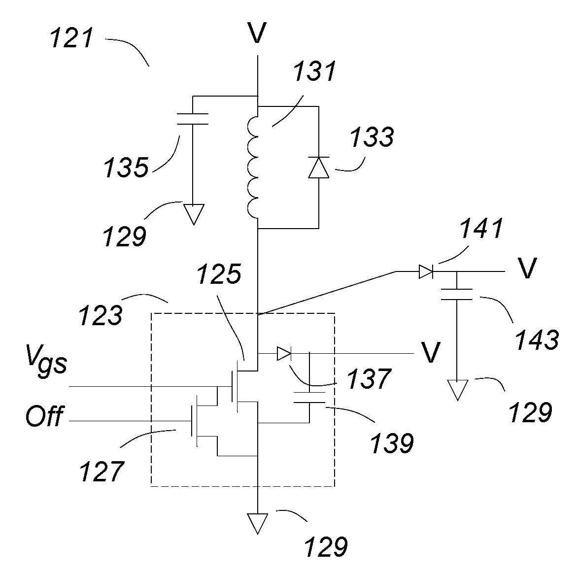
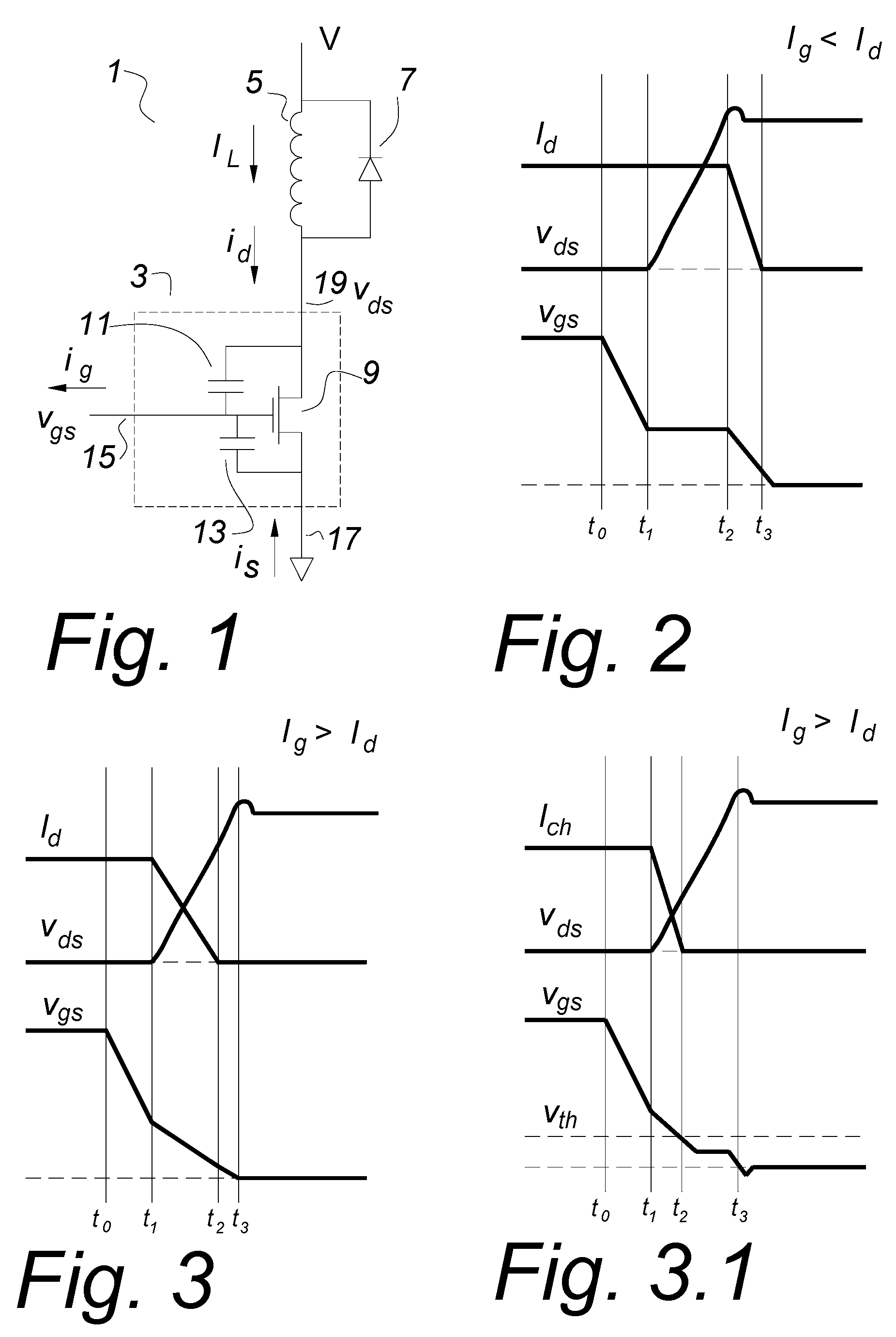
[0041]FIG. 1 shows a MOSFET as it is often shown in MOSFET application notes. A MOSFET circuit 1 comprising a MOSFET 3 is driving an inductor 5. A clamp rectifier 7 prevents spiking when the MOSFET 3 is turned off by returning the excess energy to the voltage source V if the inductive kick at turn off exceeds the voltage source V. The MOSFET 3 has a gate 15, a source 17 and a drain 19. The drain-gate parasitic capacitor 11 and the parasitic gate-source capacitance 13 are shown with an ideal MOSFET 9 that together comprise the MOSFET 3.

[0042]Often in power converters and similar circuits, the load which the MOSFET 3 is switching is inductive, so the load current IL cannot change rapidly. It is an objective of this invention to switch the MOSFET very rapidly, in the order of nanoseconds or fractions of a nanosecond. During that time, being inductively fed, the load current IL will not change appreciably. For the purposes of this discussion, it is assumed to be constant over the switch...


PUM


Abstract

Usually, in power converters, the load on a MOSFET is inductive, and the current cannot change rapidly. The drain current is the upper limit of the Miller current, so that if the gate current is larger than the drain current, the gate capacitance will continue to discharge and there can be no Miller shelf. If a parallel capacitor is used with a MOSFET, once the drain voltage starts to rise, the load current divides, placing a new lower limit on the Miller current. To drive a MOSFET with a gate current that exceeds the drain current, the circuit impedances have to be very low, suggesting a new geometry and packaging arrangement for the MOSFET and gate drive. A compatible gate turn of circuit is also disclosed.

Description

CROSS REFERENCE TO RELATED APPLICATIONS[0001]This patent application is a continuation in part application of a provisional patent application Ser. No. 60 / 319,085 filed Jan. 22, 2002 entitled “Gate Drive Method for Fast Turn-Off of MOSFETs”, a provisional patent application Ser. No. 60 / 429,990 filed Nov. 27, 2002, entitled “Gate Drive Method and Apparatus for the Fast Switching of MOSFETs”, and a patent application Ser. No. 10 / 248,438 filed Jan. 20, 2003, now abandoned, entitled “Gate Drive Method and Apparatus for Reducing Losses in the Switching of MOSFETs”.BACKGROUND OF INVENTION[0002]This invention relates to gate drive circuits for MOSFETs (Metal Oxide Silicon Field Effect Transistors), and in particular, to methods of switching MOSFETs in power converters. This invention also relates to clamping circuits used to control the overshoot due to the current flowing in the circuit inductances at the turn off of the MOSFETs.[0003]In power converters, it is important to minimize losse...

Claims


Application Information

Patent Timeline
IPC IPC(8): H03K17/04
CPCH03K17/04123H03K17/08142H01L29/0696H01L2224/16225H01L2224/48091H01L2224/49175H01L2924/13062H01L2924/13091H01L2924/00014H01L2924/00H01L2924/12032H01L2924/3011H01L2224/48137H01L2924/00011H01L2224/0401
Inventor HERBERT, EDWARD
Owner HERBERT EDWARD
Why Eureka
Try Eureka