
Interferometer apparatus for both low and high coherence measurement and method thereof

a technology of coherence measurement and interferometer, which is applied in the direction of optical radiation measurement, measurement devices, instruments, etc., can solve the problem of taking a lot of labor

Active Publication Date: 2006-01-31
FUJI PHOTO OPTICAL CO LTD
View PDF4 Cites 18 Cited by
  • Summary
  • Abstract
  • Description
  • Claims
  • Application Information

AI Technical Summary

Benefits of technology

[0012]In view of such circumstances, it is an object of the present invention to provide an interferometer apparatus for both low and high coherence measurement, which can favorably measure a transmitted wavefront of a transparent sample, while being able to yield noiseless clear interference fringe images by preventing interference fringes from being generated by reflected light from the rear face of the sample when measuring a surface wavefront from the sample surface.
[0014]Also in view of such circumstances, it is another object of the present invention to provide an interferometer apparatus for both low and high coherence measurement in a simple configuration, which can greatly alleviate labor when carrying out highly accurate length measurement by using light-wave interference, as compared with the case using the low coherent light alone.
[0023]In this case, it is preferred that one of the first and second paths of the path-matching passage be provided with a light-shielding member for preventing the luminous flux from passing when carrying out the high coherence measurement.
[0026]In this case, it is preferred that one of the first and second paths of the path-matching passage be provided with a light-shielding member for preventing the luminous flux from passing when carrying out the high coherence measurement.
[0034]a third step of irradiating the sample with the high coherent luminous flux as the measurement light by way of the reference surface of the reference lens, moving the sample along the optical axis in thus irradiated state so as to detect a position yielding a minimum number of interference fringes caused by light from the reference surface and sample, and setting the sample at thus detected position;

Problems solved by technology

When the low coherent light is used alone, however, it takes much labor to find a position where interference fringes emerge or their contrast peak position, which demands a technique for alleviating the labor by using a high coherent luminous flux together therewith.

Method used


Image

  • Interferometer apparatus for both low and high coherence measurement and method thereof
  • Interferometer apparatus for both low and high coherence measurement and method thereof
  • Interferometer apparatus for both low and high coherence measurement and method thereof

Examples


first embodiment

[0043

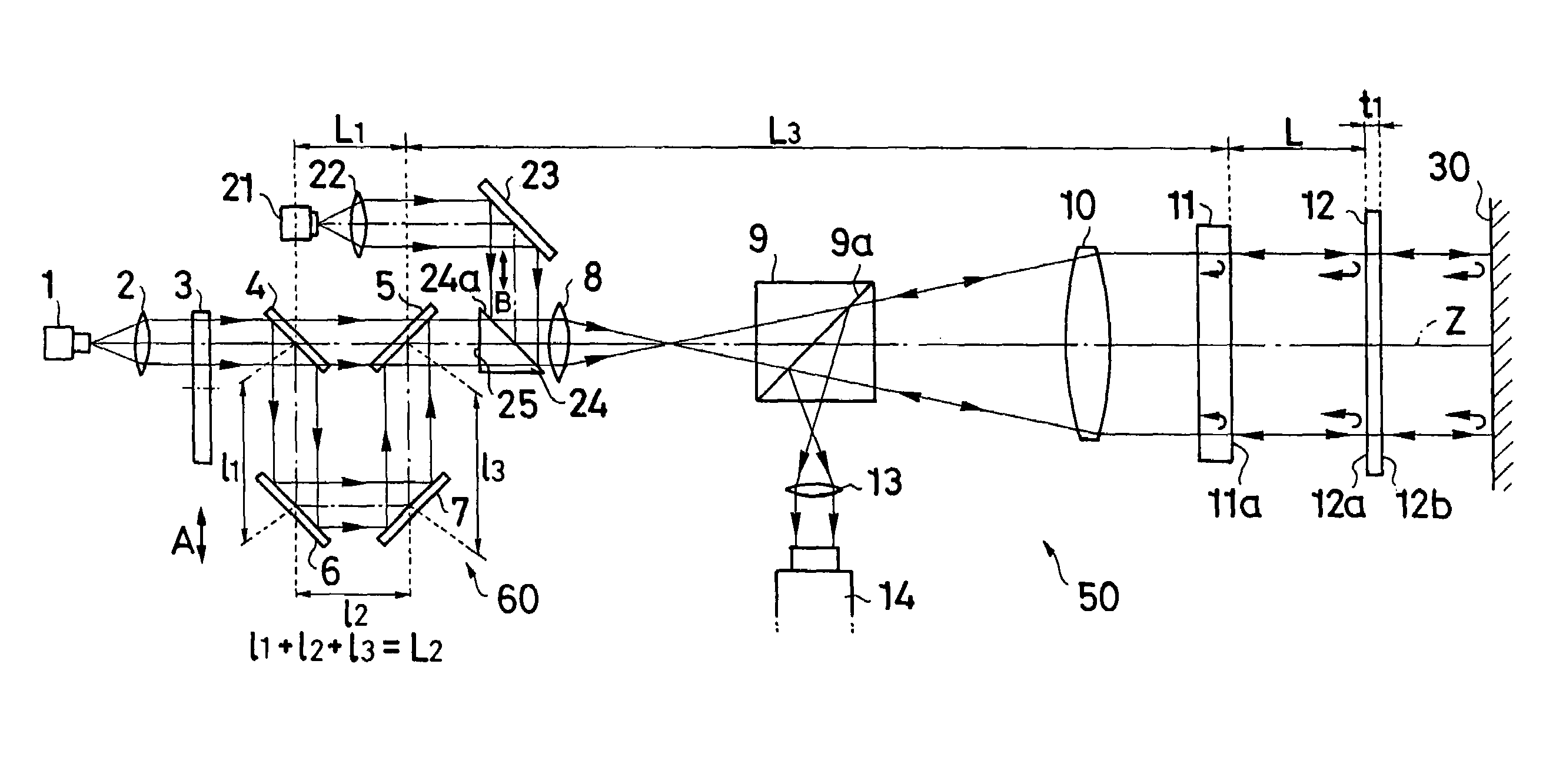
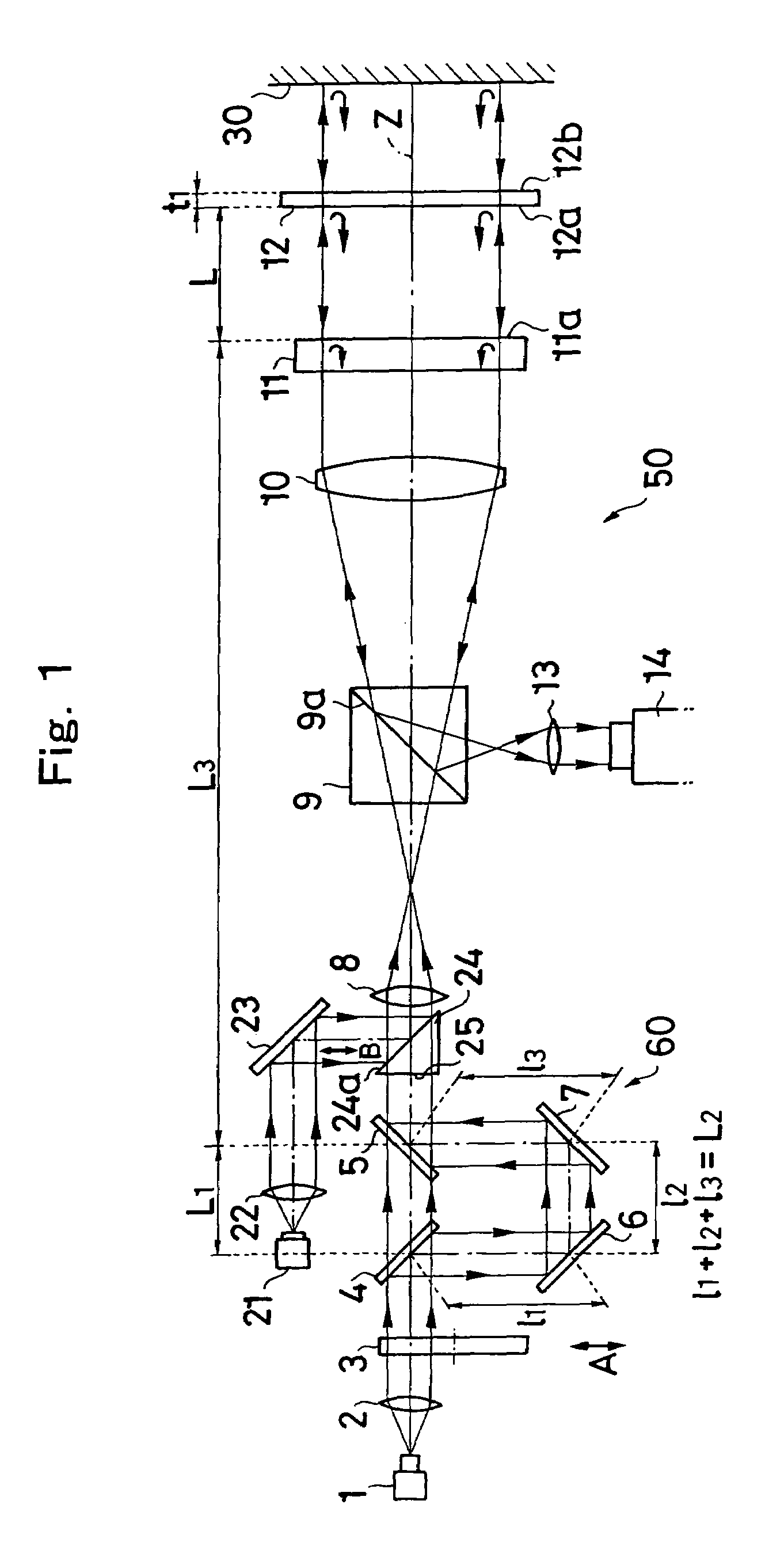
[0044]FIG. 1 is a schematic view showing the interferometer apparatus for both low and high coherence measurement in accordance with a first embodiment of the present invention.

[0045]This interferometer apparatus carries out low coherence measurement for the form of a surface 12a of a sample 12 and the like by using a low coherent luminous flux outputted from a low coherent light source 1, and also measures a transmitted wavefront of the sample 12 by using a high coherent luminous flux outputted from a high coherent light source 21 and guided such that a part of its optical path is coaxial with the low coherent luminous flux, thereby effecting interference measurement concerning an internal refractive index distribution and the like. When carrying out high coherence measurement by using the high coherent luminous flux outputted from the light source, the high coherent luminous flux is made incident on at least the sample 12 side of a path-matching passage at a position coaxial ...

second embodiment

[0091

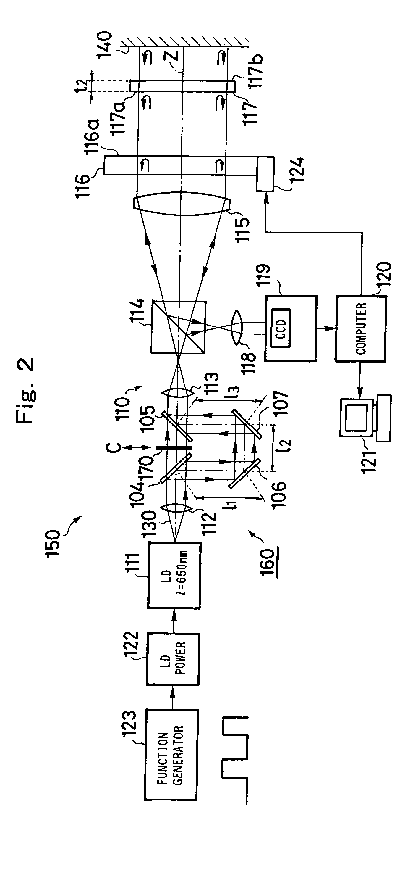
[0092]FIG. 2 is a schematic view showing the interferometer apparatus for both low and high coherence measurement in accordance with a second embodiment.

[0093]This interferometer apparatus 150 carries out low and high coherence measurement by using a light source 111 which can selectively output low and high coherent luminous fluxes. Namely, low coherence measurement which can attain information (reflected wavefront information) such as the form of a surface 117a of a sample 117 is carried out by using the low coherent luminous flux from the light source 111, and high coherent measurement which can attain information (transmitted wavefront information) such as the stress strain and refractive index distribution within the sample 117 is carried out by using the high coherent luminous flux.

[0094]Switching between the low and high coherent luminous fluxes outputted from the light source 111 is carried out by an operation of changing the wavelength of output light from the light so...

third embodiment

[0123

[0124]FIGS. 3A to 3D are views for explaining the interferometer apparatus for both low and high coherence measurement in accordance with a third embodiment of the present invention, which is configured so as to measure the radius of curvature of an optical device while using the basic configuration of the apparatus in accordance with the above-mentioned first or second embodiment.

[0125]Here, a sample 217 is an optical device having a sample surface 217a made of a concave face, whereas the radius of curvature of the concave face 217a is measured.

[0126]Therefore, a reference lens 216 is used in place of the reference plates 11, 116 employed in the above-mentioned first and second embodiments.

[0127]A procedure of measurement will now be explained with reference to FIGS. 3A to 3D.

[0128]First, as shown in FIG. 3A, the sample surface 217a of the sample 217 is irradiated with a high coherent luminous flux as measurement light by way of a collimator lens 215 (corresponding to the abov...


PUM


Abstract

A Fizeau interferometer apparatus is used for both low and high interference measurement. When irradiating a reference surface and a sample with a low coherent luminous flux, a path-matching passage divides the low coherent luminous flux into first and second paths, while the optical path length difference between the respective luminous fluxes passed through the two paths equals twice the optical distance between the reference surface and the sample. When irradiating the reference surface and the sample with a high coherent luminous flux, the luminous flux is made incident on the sample side of the path-matching passage at a position coaxial with the low coherent luminous flux.

Description

RELATED APPLICATIONS[0001]This application claims the priority of Japanese Patent Application No. 2003-011368 filed on Jan. 20, 2003, which is incorporated herein by reference.BACKGROUND OF THE INVENTION[0002]1. Field of the Invention[0003]The present invention relates to an interferometer apparatus for observing a wavefront form from a sample, an unequal optical path length interferometer apparatus such as that of Fizeau type in particular. Specifically, the present invention relates to an interferometer apparatus for both low and high coherence measurement, which can interferentially measure a surface wavefront form and a transmitted wavefront form of a sample such as a thin, flat transparent sheet, e.g., glass for liquid crystal, and various optical filters and windows, and a sphere, e.g., ball lens, at the same time.[0004]2. Description of the Prior Art[0005]As an example of techniques for measuring a plane parallel glass sheet, it has conventionally been known to use a Fizeau i...

Claims


Application Information

Patent Timeline
Patent Type & Authority Patents(United States)
IPC IPC(8): G01B9/02G01J9/02
CPCG01B9/02004G01B9/02039G01B9/02007G01B9/02072G01B9/0209G01B9/02063G01B9/02057
Inventor UEKI, NOBUAKI
Owner FUJI PHOTO OPTICAL CO LTD
Learn More