Retention module, heat sink and electronic device

a technology of heat sink and heat sink, which is applied in the direction of indirect heat exchangers, electrical apparatus construction details, lighting and heating apparatus, etc., can solve the problems of large influence of heat from the cpu on the chip set heating value, which was conventionally negligible, and has become non-negligent, so as to improve the heating value of the cpu and improve the performan

Inactive Publication Date: 2006-01-31
FUJITSU LTD
View PDF20 Cites 69 Cited by
  • Summary
  • Abstract
  • Description
  • Claims
  • Application Information

AI Technical Summary

Benefits of technology

[0006]However, as the chip set has more improved performance, influence of the heating value from the chip set, which was conventionally negligible, has become non-negligible. As the heating value of the CPU increases, the heat from the CPU greatly affects the chip set near the CPU. Therefore, the protection of the chip set from thermal malfunctions and damages has needed a heat radiator means for the chip set, which was n...

Problems solved by technology

However, as the chip set has more improved performance, influence of the heating value from the chip set, which was conventionally negl...

Method used


Image

  • Retention module, heat sink and electronic device
  • Retention module, heat sink and electronic device
  • Retention module, heat sink and electronic device

Examples


Embodiment Construction

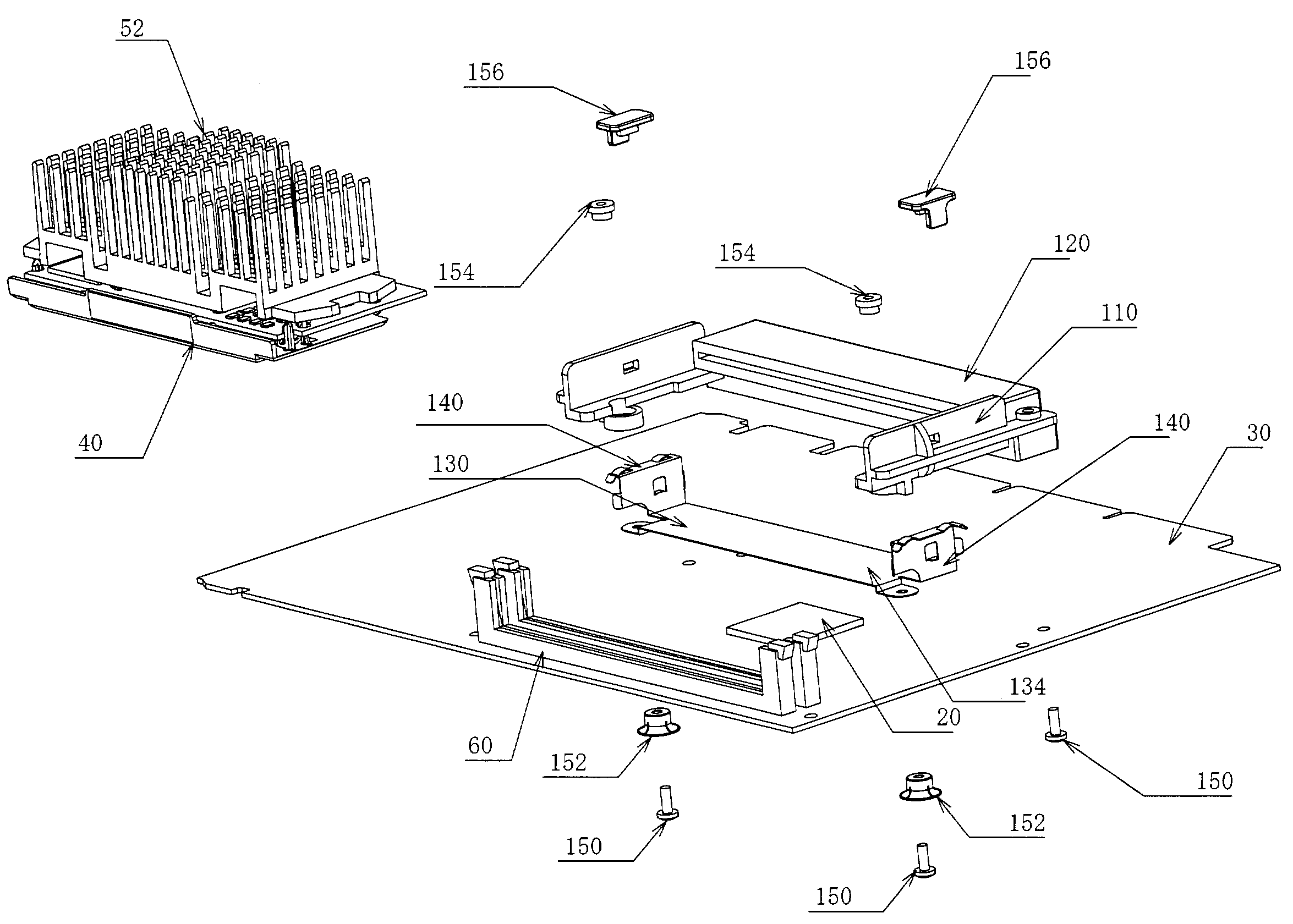
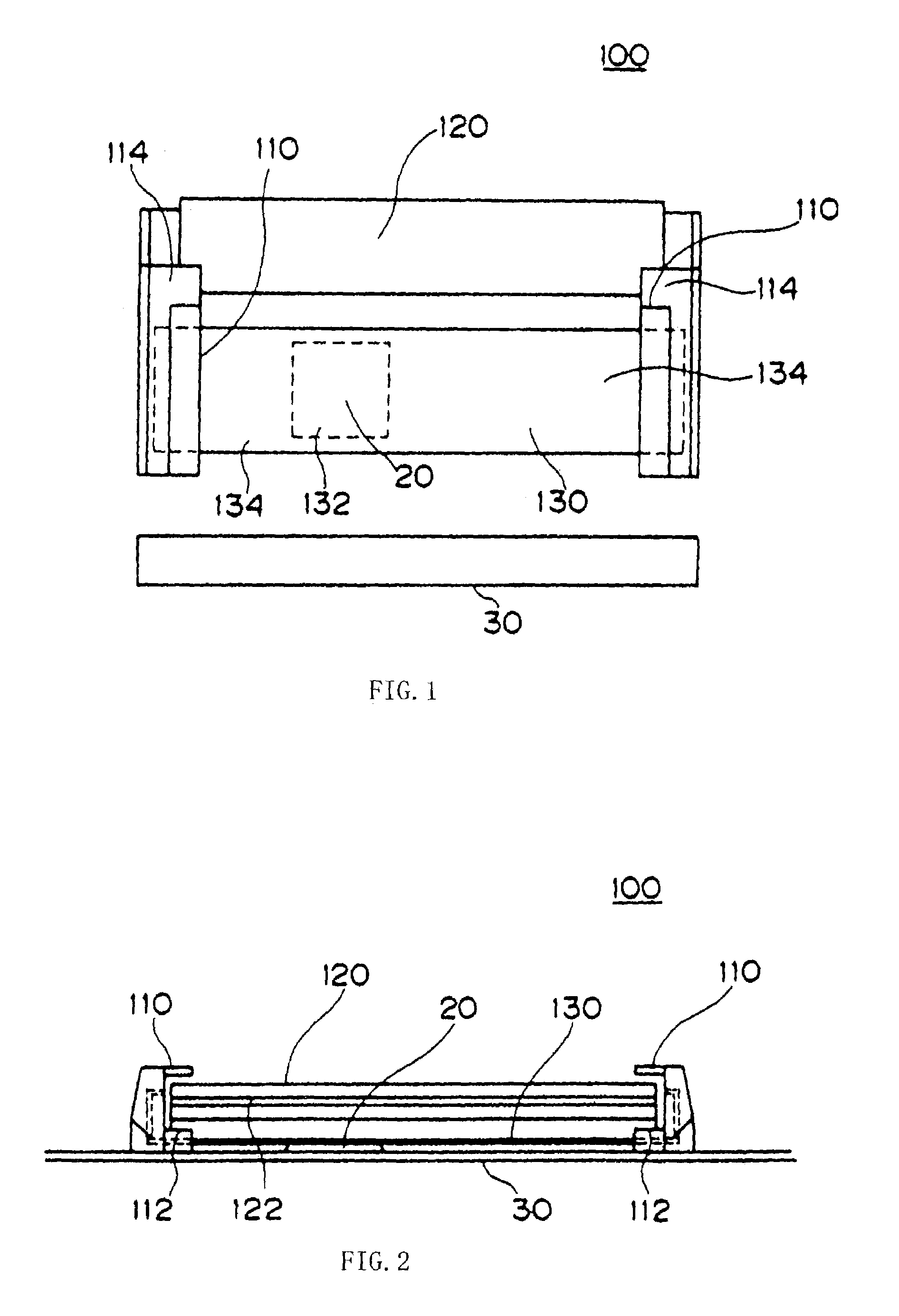
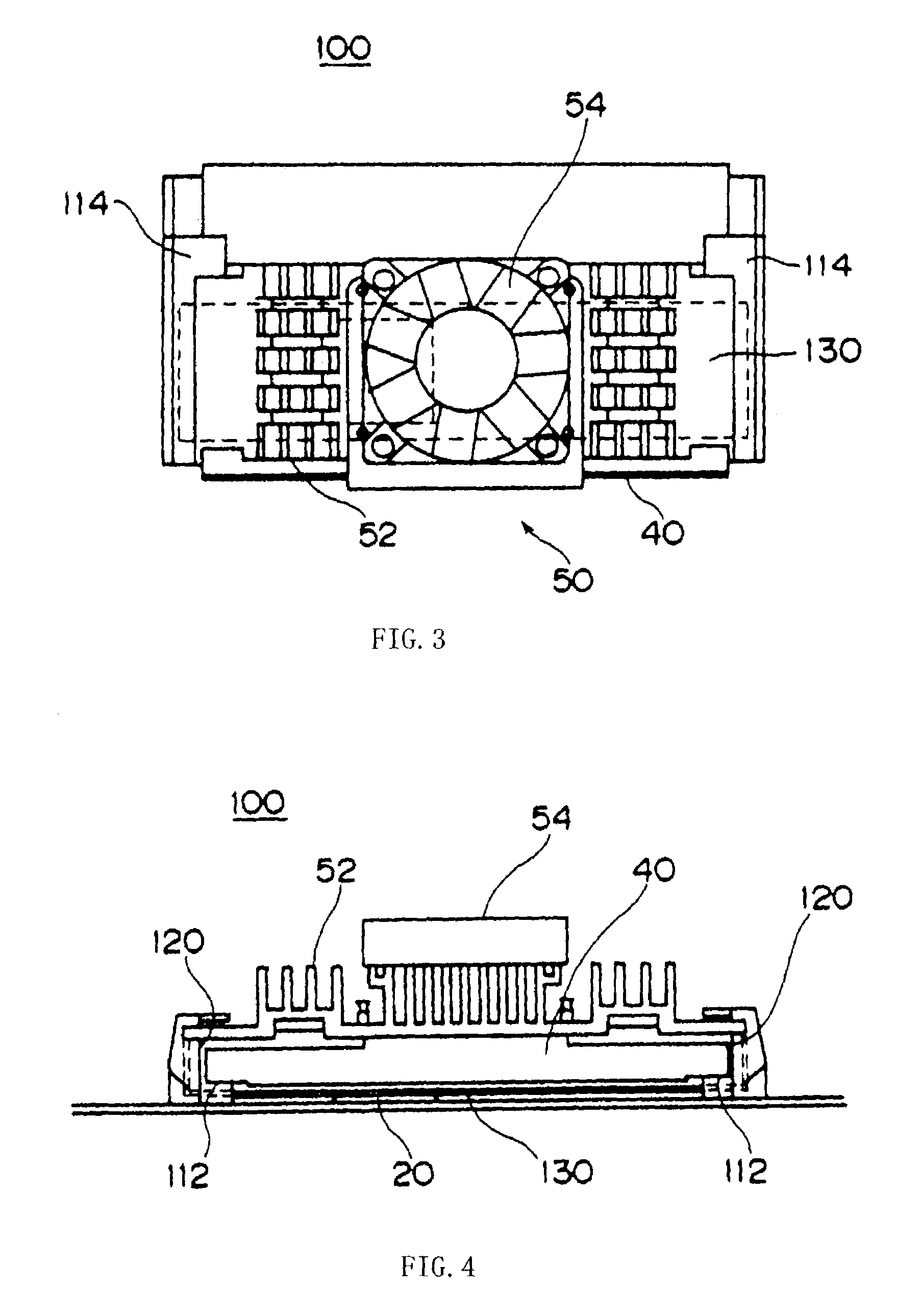
[0028]A detailed description will now be given of an embodiment according to the present invention with reference to FIGS. 1–4. FIG. 1 is a schematic plane view of a retention module 100 before a CPU 40 and a fan heat sink 50 are mounted. FIG. 2 is a schematic sectional view of the retention module 100 shown in FIG. 1. FIG. 3 is a schematic plane view of the retention module 100 after the CPU 40 and fan heat sink 50 are mounted. FIG. 4 is a schematic sectional view of the retention module 100 shown in FIG. 3. FIGS. 5 and 6 are exploded views for explaining an engagement among the CPU 40, cooling fins 52 (without a fan) and retention module 400, viewed from different angles.

[0029]The retention module 100 electrically connects the CPU 40 to the motherboard 30, and includes a pair of standing holding parts 110, slot 120, heat sink 0.130, and connecting part 136. This embodiment mounts the retention module 100 onto the motherboard 30 in a desktop type PC 200 as one example of an electro...


PUM


Abstract

It is an object of the present invention to provide a retention module, a heat sink and electronic apparatus for effectively the heat from a chip set. The retention module for a CPU is provided with a heat sink for the chip set.

Description

FIELD OF THE ART[0001]The present invention relates generally to heat radiator mechanisms, and more particularly to a heat radiator mechanism for radiating the heat from a circuit element mounted in an electronic apparatus. The present invention is suitable for a retention module (also referred to as a CPU socket, a retention kit or a retention tool) for electrically connecting a CPU to a motherboard and for fixing the CPU onto the motherboard, and the inventive electronic apparatus broadly covers personal computers (PCs) of desktop type including a tower type, measurement devices, control devices, and the like.BACKGROUND OF THE INVENTION[0002]A CPU (Central Processing Unit) in a computer handles data inputs / outputs, executes commands, controls each component, and thus directly affects computer performance. A current CPU uses a laterally long and wide cartridge called Slot 1 Type as seen in U.S. Intel Pentium II.[0003]A computer exhibits higher performance as it mounts a higher CPU;...

Claims


Application Information

Patent Timeline
IPC IPC(8): H05K7/20H01L23/367H01L23/40H05K7/14
CPCH01L23/3675H01L23/40H01L23/4093H05K7/1431H01L2924/0002H01L2924/00
Inventor KASHIWAGI, TOSHIYUKIKATOU, HIROKATSU
Owner FUJITSU LTD
Why Eureka
Try Eureka