Reading method and apparatus for a three-dimensional information carrier

a three-dimensional information carrier and data reading technology, applied in the field of scanning techniques, can solve the problems of crosstalk affecting the signal-to-noise ratio, the information capacity of a stacked information carrier is limited in practice to 10sup>10, and the cost effectiveness of cost reduction, so as to achieve significant increase in the number of information layers and reduce the crosstalk between the addressed information layer and all other information layers.

Inactive Publication Date: 2006-01-31
D DATA
View PDF6 Cites 33 Cited by
  • Summary
  • Abstract
  • Description
  • Claims
  • Application Information

AI Technical Summary

Benefits of technology

[0019]The main object of the present invention is to provide such a method and an apparatus that enables crosstalk between an addressed information

Problems solved by technology

This method requires precision optical, mechanical and electronic components, as well as high quality media, and therefore its capacity is limited by cost effectiveness.
This approach suffers from the following drawbacks:(1) data regions are light reflective, resulting in undesirable multiple reflection when reading out the stored information;(2) power losses at each information disk during the propagation of reading and reflected beams to and from the internal disks, respectively;(3) interference of beams reflected from different disks;(4) diffraction of beams passing through the disk;(5) beam distortions due to the optical aberrations, which appear when changing the optical path of the reading beam within the carrier to read different information planes (i.e. different disks); and(6) high quality optical adhesives required for assembling the stack of disks, having no aberrations, bubbles, separations, inclusions, as well as no mechanical, thermal and chemical impact on the discs.
The information capacity of a stacked in

Method used


Image

  • Reading method and apparatus for a three-dimensional information carrier
  • Reading method and apparatus for a three-dimensional information carrier
  • Reading method and apparatus for a three-dimensional information carrier

Examples


Embodiment Construction

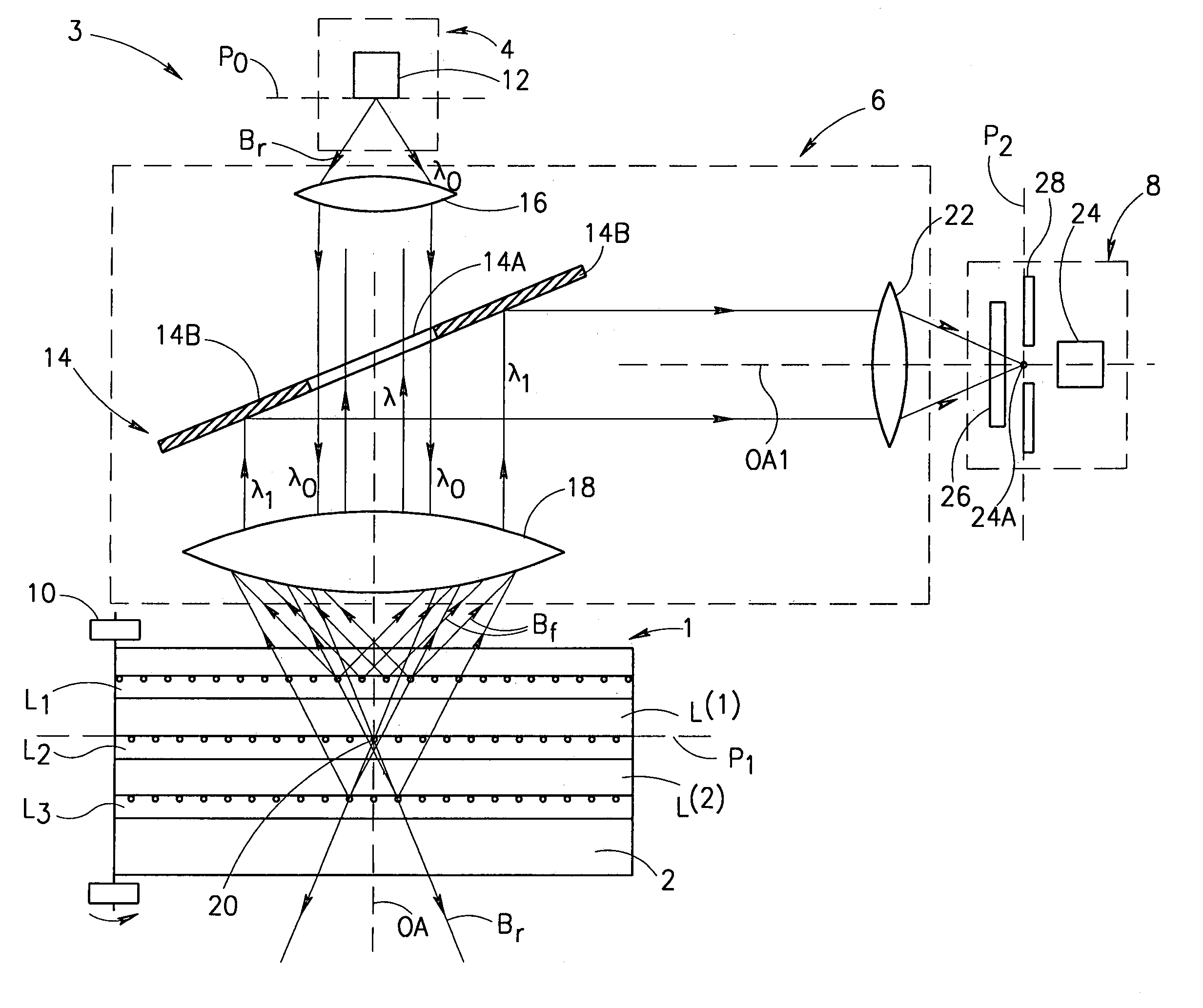
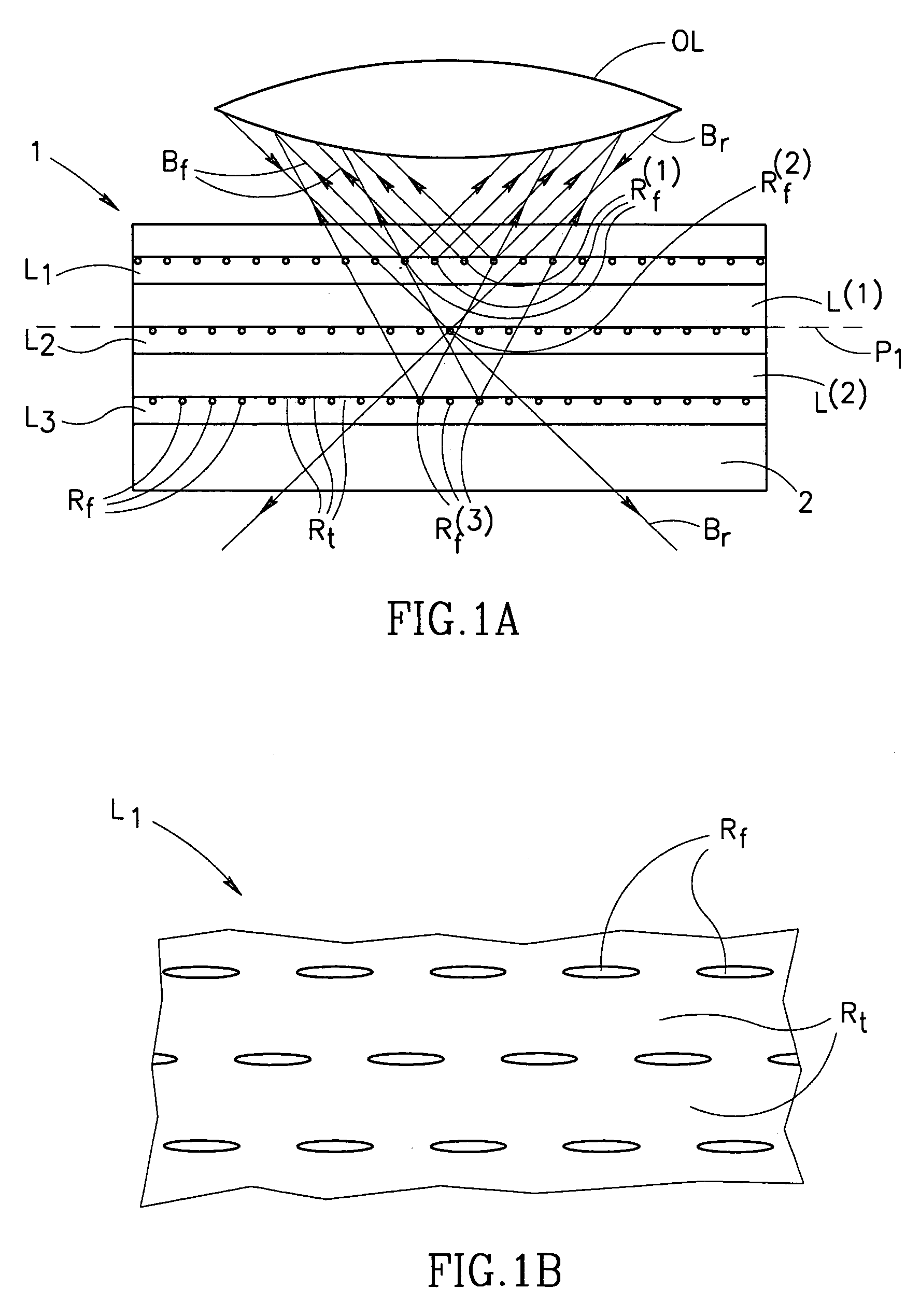
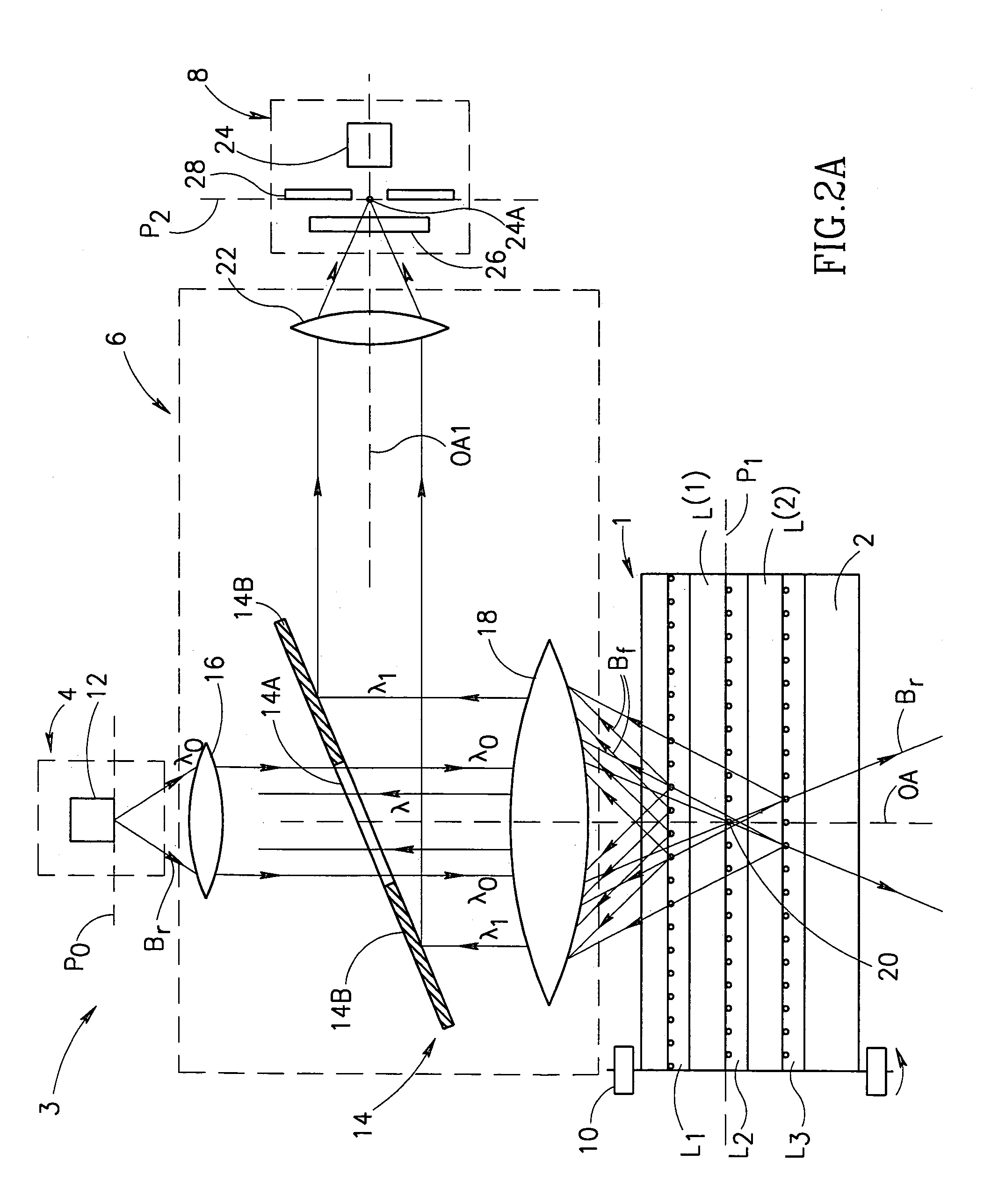
[0053]In order to more clearly illustrate the unique feature of the present invention, it would be reasonable to consider a three-dimensional optical memory device that utilizes fluorescent data regions, i.e. regions excitable in response to predetermined incident radiation. FIG. 1a schematically illustrates a three-dimensional optical disk, generally designated 1, that comprises several information layers, for example, three layers L1, L2 and L3, formed on a substrate 2. Thickness d of each information layer is approximately 0.3–20 μm. The adjacent information layers are spaced by intermediate layers L(1) and L(2), respectively, made of substantially optically transparent material. Thickness L of each intermediate layer is approximately 5–500 μm.

[0054]As better shown in FIG. 1b, information stored in the information layer, for example layer L1, is in the form of a pattern having a plurality of spaced-apart data regions, generally at Rf, containing fluorescent material, which are sp...


PUM


Abstract

A method and apparatus for reading in a three-dimensional information carrier are presented. The three-dimensional information carrier is formed with a plurality of spaced-apart data regions, each surrounded by surrounding-regions. The data regions are made of a material capable of generating an output excited radiation, when interacting with a predetermined incident exciting radiation, while the surrounding regions are substantially optically transparent. The apparatus comprises an illumination unit, a light directing unit and a detector unit. The illumination unit produces a scanning beam of the incident radiation. The light directing unit projects the incident radiation onto a scan region located in an addressed plane inside the carrier and collects the output radiation. The light directing unit is capable of picking up a predetermined portion of the collected output radiation, so as to provide spatial separation of the output radiation components produced by the data regions located in the addressed plane and the output radiation components produced by the data regions located at any other location inside the carrier.

Description

[0001]This application claims the benefit of 60 / 064,298 filed Nov. 05, 1997.FIELD OF THE INVENTION[0002]The present invention is in the field of scanning techniques and relates to a method and an apparatus for reading / recording data in a three-dimensional information carrier.BACKGROUND OF THE INVENTION[0003]In most of the known information carriers, such as magnetic and optical disks, tapes, cards, etc., the stored information is distributed within a surface of the carrier. The capacity of a device of this class (i.e. two-dimensional memory device) is limited by the surface area and is inverse proportional to the second order of reading radiation wavelength.[0004]There is increasing demand for cheap and reliable large capacity carriers of digital information for computers, video systems, multimedia etc., and for high-density data storage in optical media, particularly for CD-ROM data and documents and image / movie storage in CD-sized disks. Such a carrier should have a storage capaci...

Claims


Application Information

Patent Timeline
IPC IPC(8): G11B7/00
CPCG11B7/1362G11B7/1395G11B2007/0013
Inventor GLUSHKO, BORISKRUPKIN, VLADIMIR
Owner D DATA
Why Eureka
Try Eureka