
Excess air factor control of diesel engine

a technology of excess air factor and diesel engine, which is applied in the direction of electric control, machines/engines, mechanical equipment, etc., can solve the problems of nitrogen oxide generation, combustion temperature drop, etc., and achieve the effect of preventing the change of engine output torque and increasing the accuracy and response of excess air factor control

Inactive Publication Date: 2006-02-07
NISSAN MOTOR CO LTD
View PDF14 Cites 96 Cited by
  • Summary
  • Abstract
  • Description
  • Claims
  • Application Information

AI Technical Summary

Benefits of technology

[0016]Therefore, when shifting the target excess air factor from 1.4 or more to 1.0 or a lower value for regeneration of the NOx trap catalyst or diesel particulate filter, the most responsive way of control to achieve the new target excess air factor is to increase the fuel injection amount.
[0019]There is also a different approach to attain the new target excess air factor in a short time but without increasing the engine output torque. This is the delay compensation control of the intake air amount. In this control, the delay in the intake air amount control is previously assessed and compensated by a delay compensation process based on the assessed delay.
[0021]It is therefore an object of this invention to increase the accuracy and response of the excess air factor control while preventing the change in the engine output torque.

Problems solved by technology

EGR brings about a decline of combustion temperature and reduces the generation of nitrogen oxides (NOx) as a result.

Method used


Image

  • Excess air factor control of diesel engine
  • Excess air factor control of diesel engine
  • Excess air factor control of diesel engine

Examples


Embodiment Construction

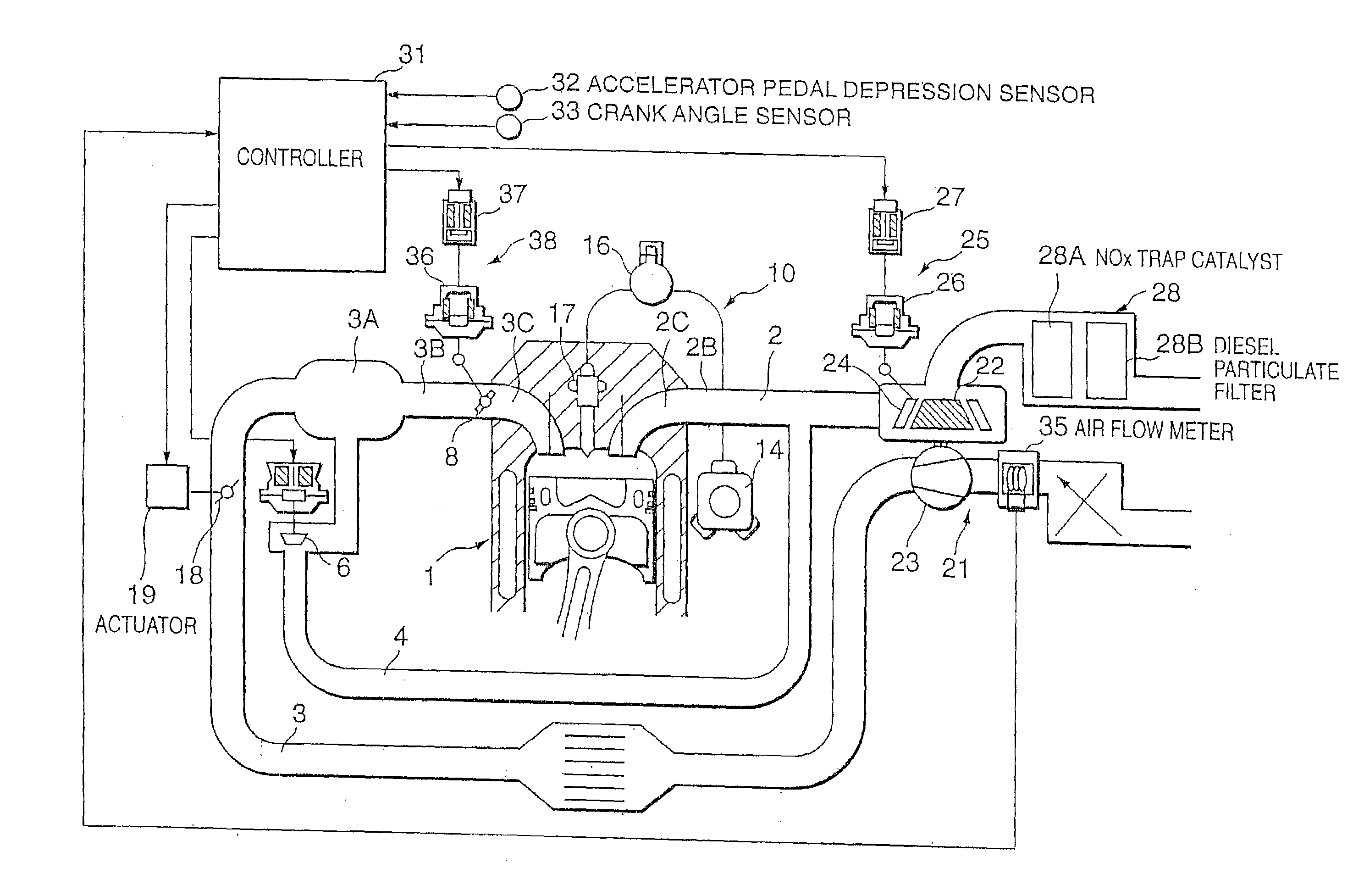
[0043]Referring to FIG. 1 of the drawings, a multi-cylinder diesel engine 1 is provided with an exhaust passage 2 and an intake passage 3.

[0044]The intake passage 3 is connected to an intake port 3C provided for each cylinder via an intake manifold 3B which branches off from a collector 3A.

[0045]The exhaust gas passage 2 is connected to an exhaust port 2C provided for each cylinder via an exhaust manifold 2B.

[0046]Air from a compressor 23 of a variable capacity turbocharger 21 is supplied to the intake passage 3.

[0047]The variable capacity turbocharger 21 drives the compressor 23 by rotation of an exhaust gas turbine 22 installed in the exhaust passage 2.

[0048]The exhaust gas turbine 22 is provided with a variable nozzle 24 driven by an actuator 25 at the inlet of a scroll.

[0049]In the low rotation speed region of the diesel engine 1, the variable nozzle 24 increases the flow velocity of the exhaust gas which flows into the exhaust gas turbine 22 by narrowing the opening, and in the...


PUM


Abstract

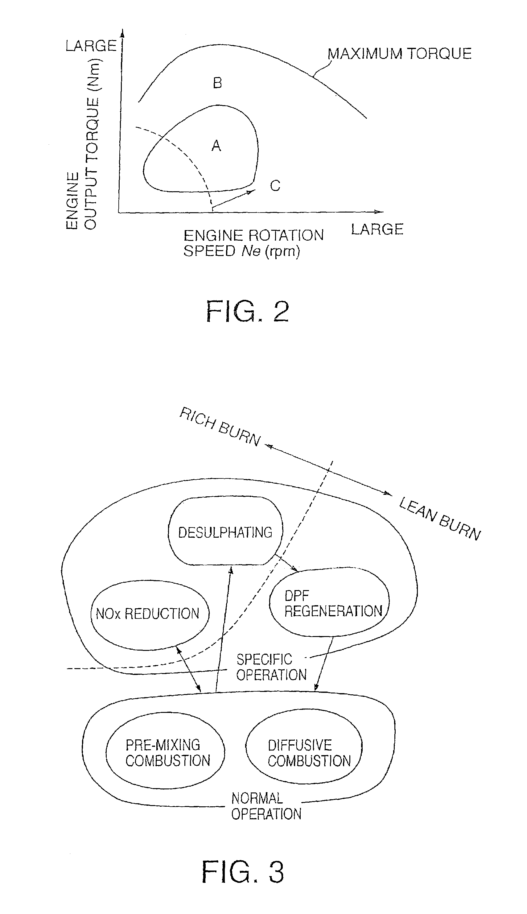
A diesel engine (1) provided with a NOx catalyst (28A) and a diesel particulate filter (28B) performs lean burn operation during normal running, rich burn operation during regeneration of the NOx catalyst (28A), operation under the stoichiometric air-fuel ratio during desulphating of the NOx catalyst (28A), and operation under a slightly lean air-fuel ratio to regenerate the filter after desulphating of the NOx catalyst (28A). When the lean burn operation is applied, a controller (31) first controls the fuel injection amount, and controls an air supply amount based on the fuel injection amount. When rich burn operation is applied, the controller (31) first controls the air supply amount and controls the fuel injection amount based on the air supply amount. Due to this control, the response of the excess air factor control is enhanced while preventing torque fluctuation accompanying the variation of the target excess air factor.

Description

FIELD OF THE INVENTION[0001]This invention relates to control of the excess air factor of a diesel engine.BACKGROUND OF THE INVENTION[0002]Exhaust gas purification techniques in diesel engines for vehicles are divided roughly into two categories, one for improving combustion of the air-fuel mixture so as to reduce generation of noxious substances, and the other one for purifying the noxious substance contained in the exhaust gas.[0003]As to the former techniques, Tokkai Hei 6-346763 published by the Japanese Patent Office in 1994 discloses performing exhaust gas recirculation (EGR) and making the ignition lag, i.e., the lag between the start of fuel injection and the start of combustion, considerably longer.[0004]EGR brings about a decline of combustion temperature and reduces the generation of nitrogen oxides (NOx) as a result.[0005]If the ignition lag is made considerably longer, the engine heat generation pattern becomes single stage and mixing of air and fuel is promoted, so the...

Claims


Application Information

Patent Timeline
Patent Type & Authority Patents(United States)
IPC IPC(8): F01N3/00F02B37/00F01N3/02F01N3/08F01N3/20F01N3/24F01N3/28F02B1/12F02B3/06F02B37/12F02D9/02F02D9/04F02D21/08F02D23/02F02D41/00F02D41/02F02D41/04F02D41/30F02D41/40F02D43/00F02M25/07
CPCF01N3/0842F02D41/005F02D41/0275F02D41/028F02D41/40Y02T10/47F02B1/12F02B3/06F02B29/0406F02D41/0007F02D41/0065F02D41/029F02D41/3035F02D2041/0022F02D2250/32F02M25/0707F02M25/0713F02M25/0718Y02T10/44F01N2570/04F02M26/05F02M26/10F02M26/15Y02T10/40F02D45/00
Inventor SHIRAKAWA, TAKASHI
Owner NISSAN MOTOR CO LTD
Learn More