[0008]In accordance with a preferred embodiment of the present invention, there is provided methods for altering residual tensile stresses in a metal surface, especially in those surfaces which, as machined or as welded, have high tensile stresses to reduce the tensile stresses or convert the tensile stresses to compressive stresses in the metal surface. Long-term stress benefits of the present invention are achieved by using the cumulative action of mechanically-induced acoustic cavitation of a liquid in contact with the
surface layer of the metal whose stress is to be altered. Particularly, a mechanical cavitation transducer
assembly is provided to afford intense cavitation of a liquid near the transducer face when vapor bubbles are formed where the
local pressure in the flow field is made to fall below the saturation pressure due to the mechanically-induced
pressure wave. Local boiling therefore occurs without the addition of heat. The bubbles formed during the rarefaction portion of the transducer's motion period rapidly collapse during the subsequent high-speed compression portion of the period, in turn causing localized high-energy compressive waves in the liquid. These waves travel toward the metal surface, where they provide the required local mechanical impulses to compress the nearby
solid metal surface sufficiently to provide, after a predetermined
processing time, localized elastic and plastic tensile microstrain. This localized tensile strained surface material is constrained by the surrounding body of undeformed material so that the remaining elastic portion of the microstrain in the deformed
surface layer has reduced tensile stress, which convert to compression stresses when the applied
hydraulic pressure force resulting from the collapse of each bubble or group of bubbles is removed. That is, by effectively water-hammering on the ductile metal surface, the portion impacted by the
pressure wave stresses plastically in the treated zone by tensile microstrain. Since this zone is integral with and mechanically constrained by the surrounding work surface, the tensile stresses are reduced and, importantly, the sign of the stress in the zone may change from tensile to compressive, as desired, when the applied stress from the
pressure wave is released. After a sufficient period of treatment, the underlying area beneath the treated zone goes into tension to maintain the required balance of
internal forces. Thus, the integrated effect of many mechanically induced cavitation bubbles collapsing over a localized predetermined area and for a predetermined time provides the desired magnitude of compressive surface
residual stress. The altered stress effect extends to a controlled depth in the work piece without excessively deforming the surface of the material in which it is generated and is self-limiting in this regard due to the controlled bubble size generated by the bubble cavitation implosion mechanism.
[0010]By mitigating the detrimental effects of tensile surface
residual stress in structural components,
stress corrosion cracking initiation in structural materials may be prevented, particularly those exposed to high-temperature oxygenated water in boiling water
nuclear reactor environments. Fatigue
crack initiation is also minimized, particularly for those components subject to high-fatigue duty, such as jet pump riser brace to vessel weld repairs in boiling water nuclear reactors. It will be appreciated that the present methods produce reduced or compressive surface and near-surface residual stresses with significantly lower plastic strain in the exposed
surface rendering the final cold-work condition of the surface acceptable, the degree of cold-work being controlled to be less than the threshold for
stress corrosion cracking.
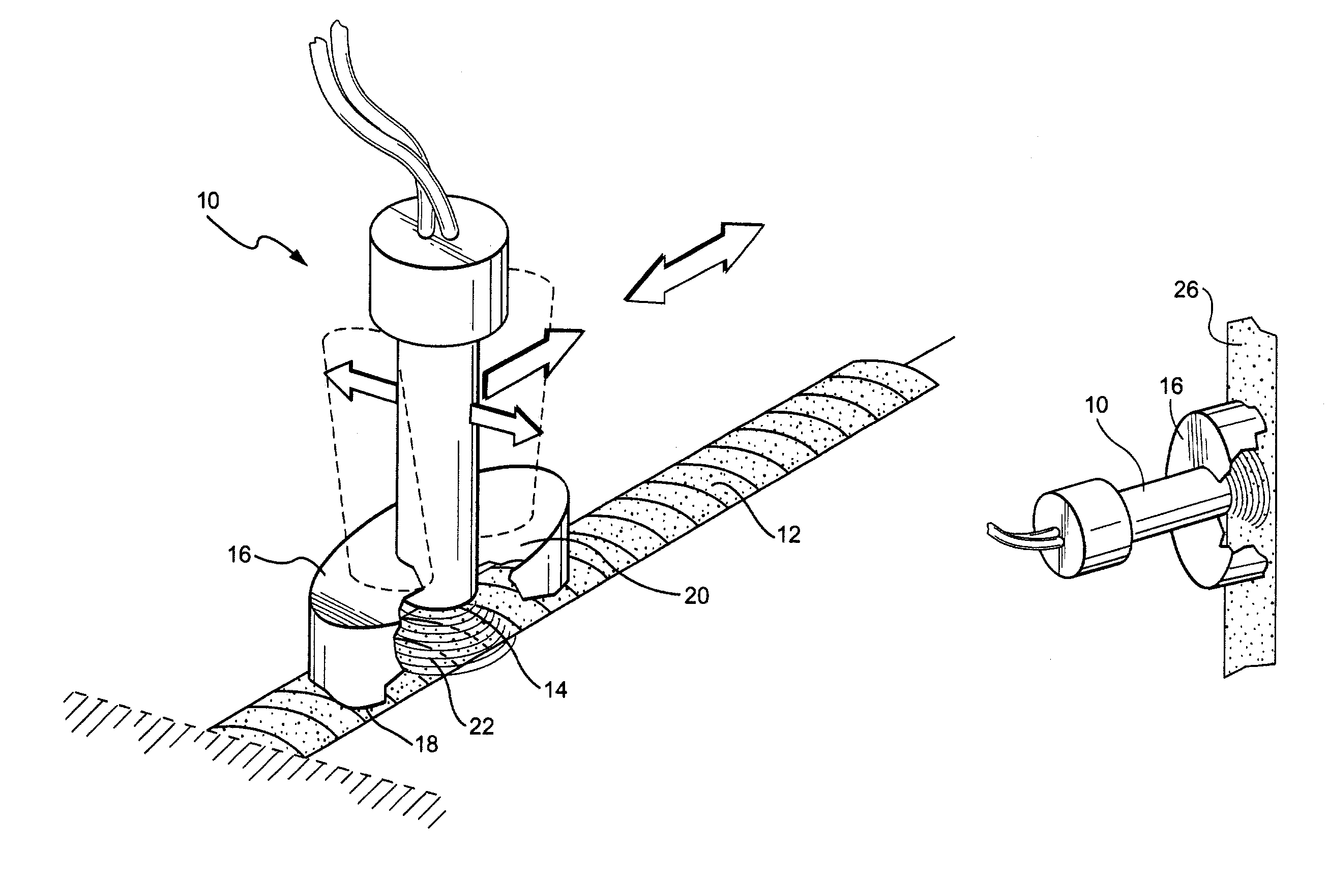
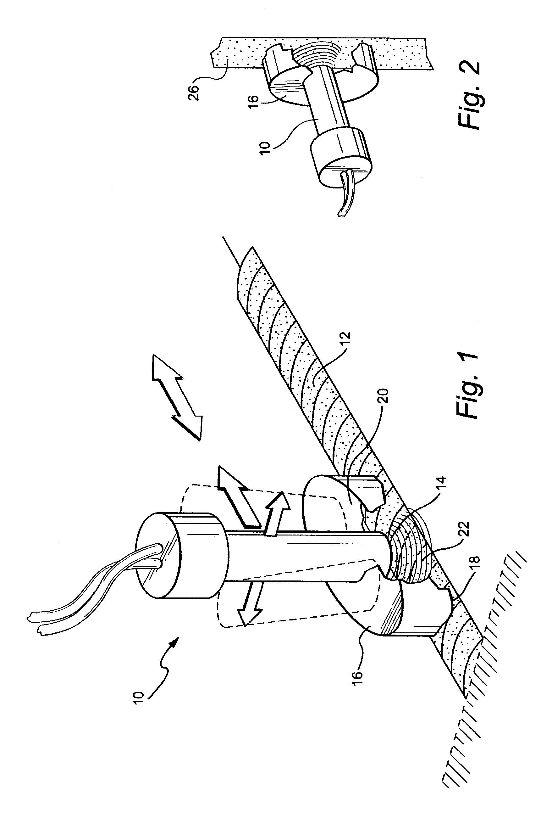
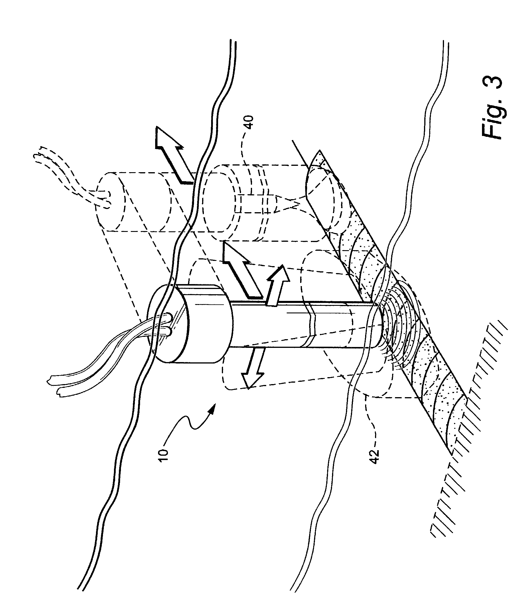
[0012]In a further preferred embodiment according to the present invention, there is provided a method for altering residual tensile stresses in a metal surface, comprising the steps of (a) submerging an ultrasonic transducer in a liquid, (b) generating a pressure wave by operation of the transducer, (c) inducing a
local pressure in the liquid adjacent the metal surface below the saturation pressure to create cavitation bubbles, and (d) subsequent to step (c), inducing a pressure wave to collapse the cavitation bubbles to
impact the metal surface to reduce tensile stresses or convert the tensile stresses in the metal surface to compressive stresses.

