Methods for calefaction densification of a porous structure

a porous structure and densification method technology, applied in the field of densification methods of porous structures, can solve the problems of poor energy yield, non-optimized densification rates, and densification rate decline, and achieve the effect of increasing porosity

Inactive Publication Date: 2006-02-07
COMMISSARIAT A LENERGIE ATOMIQUE ET AUX ENERGIES ALTERNATIVES
View PDF12 Cites 22 Cited by
  • Summary
  • Abstract
  • Description
  • Claims
  • Application Information

AI Technical Summary

Benefits of technology

[0004]The invention applies to the densification of a porous material, in particular felts, textiles, needle-punched and three-directional preforms, can be advantageously used because of their high mechanical resistance, their excellent thermal insulating ability, and their good resistance to shock and abrasion, for producing thermal shielding, brake disks and nozzle throats.

Problems solved by technology

poor energy yield, since 50 to 90% of the heating energy passes into evaporation without being used in the cracking operation, and
non-optimized densification rates, since the thermal gradients are very high and the densification rate diminishes as the thermal gradient increases.

Method used


Image

  • Methods for calefaction densification of a porous structure
  • Methods for calefaction densification of a porous structure
  • Methods for calefaction densification of a porous structure

Examples


example 1

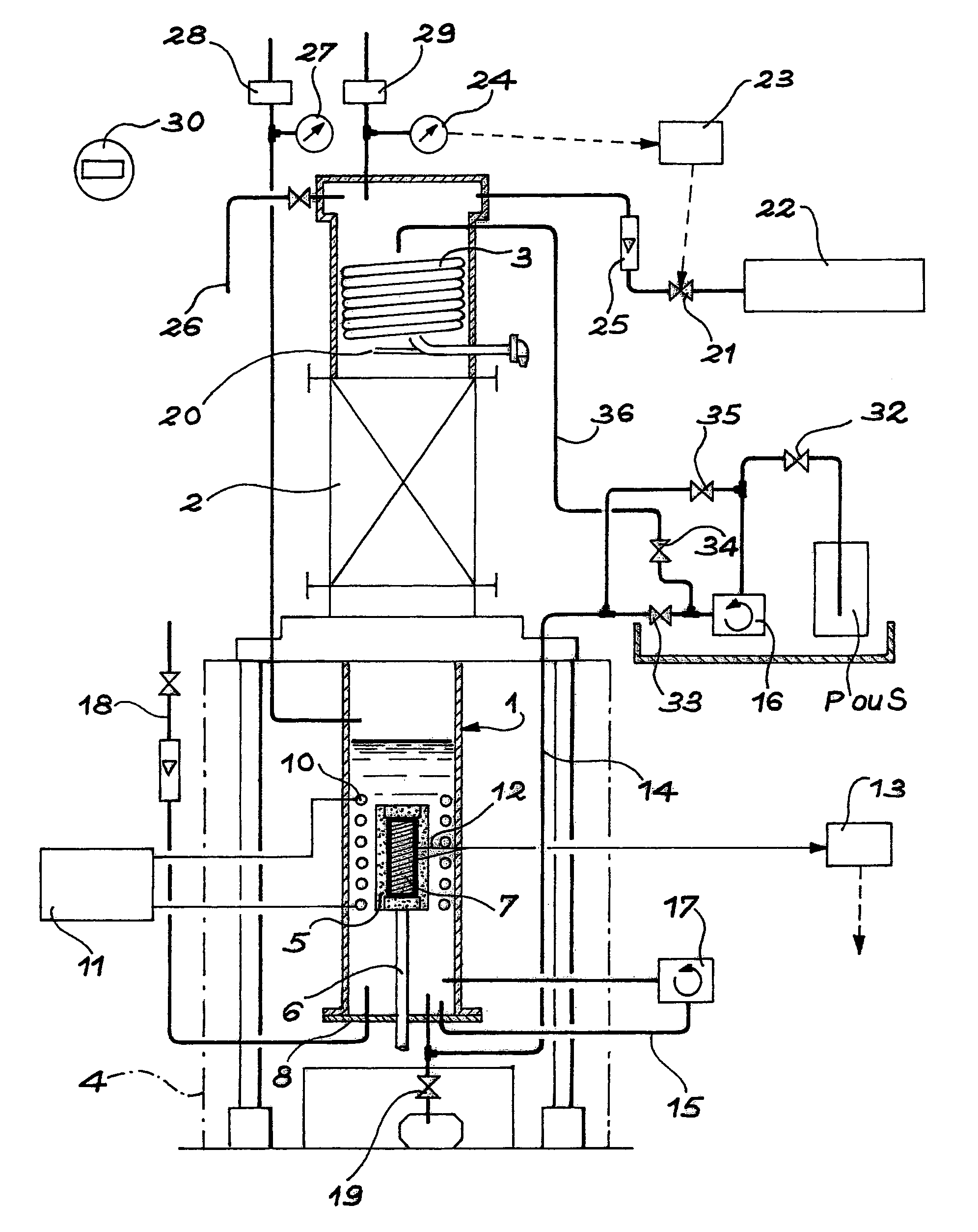
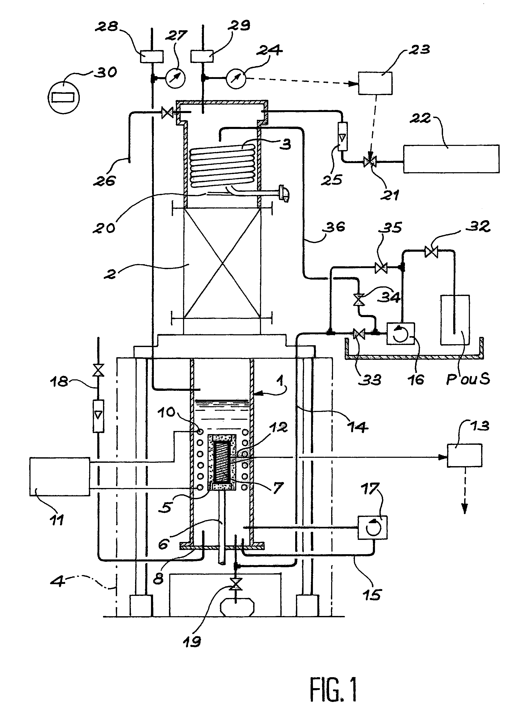
[0070]The reactor used has an inside diameter of 200 mm, an height of 300 mm. The inductor that is arranged inside the reactor, has a height of 150 mm and is comprised of six turns having inside and outside diameters having values of 175 mm and 195 mm, respectively.

[0071]The susceptor used has a diameter-of 80 mm and a height of 100 mm. It is entirely covered using three pieces of carbon felt (density 0.40 to 0.45) to be densified:[0072]a hollow cylinder having inside and outside diameters, respectively, of 80 and 120 mm and a height of 100 mm, covering its lateral surface;[0073]two disks having a diameter of 120 mm and a thickness of 20 mm covering the top and bottom parts of the two flat surfaces.

[0074]The system is covered with a filter formed of two layers of polytetrafluorethlylene GORE-TEX®, having the following characteristics:[0075]thickness of one layer: 0.2 mm;[0076]filtration: allows passage only of particles of a diameter less than 7.5 μm;[0077]permeability: 1 Darcy (or ...

example 2

[0089]This example relates to the densification of small pieces of carbon. Heating is done resistively.

[0090]The heating element is a bar of graphite 3 mm in diameter. It is surrounded by the sample to be densified, which is a tube of carbon felt (density 0.1) 2 cm in diameter and 3 cm in height. The system is enveloped in a filter formed of two layers of GORE-TEX® tissue, as in Example 1.

[0091]The pressure is set at 0.1 MPa. The temperature increase is done at a rate of 1,000° C. / h up to 1,100° C. The temperature is held at 1,100° C. for 30 minutes, then lowered at a rate of 1,000° C. / h.

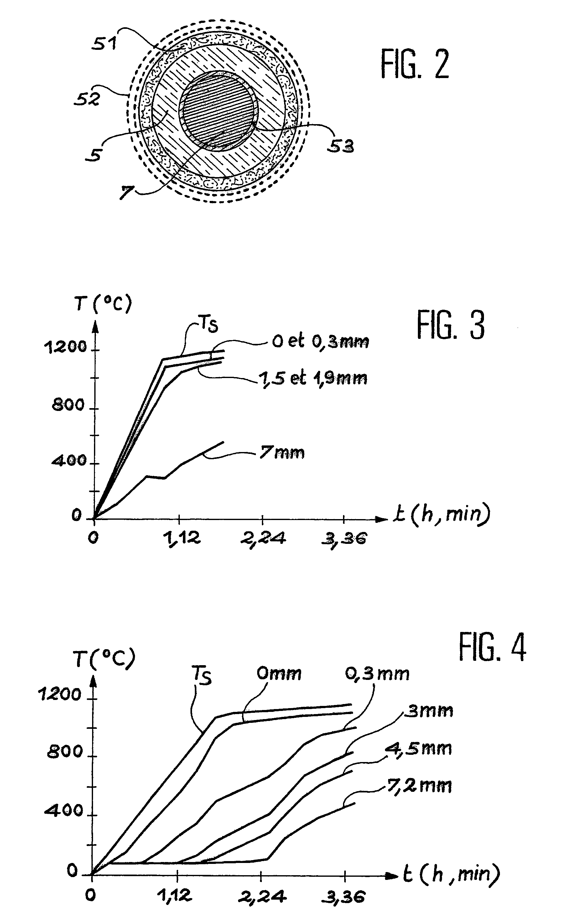
[0092]The results are as follows:[0093]the rate of densification is 4 mm / h;[0094]the energy consumed is 110 kWh / kg of carbon deposited;[0095]the density is 1.8.

[0096]By comparison, if there were no GORE-TEX® filter, under the same conditions:[0097]the rate of densification is 0.6 mm / h;[0098]the energy consumed is 1,400 kWh / kg of carbon deposited;[0099]the density is 1.8.

[0100]FIGS. 3 and 4 represent...


PUM

PropertyMeasurementUnit
thicknessaaaaaaaaaa
thicknessaaaaaaaaaa
thicknessaaaaaaaaaa

Abstract

The invention relates to a film-boiling densification method for a porous structure (mixed gas-liquid method) (5) consisting in immersing of the porous structure into a liquid precursor, a hydrocarbon, for example, and heating the system in order to deposit the decomposition product of said liquid precursor, for example carbon, into the pores of the porous structure, characterized in that the flow of the liquid precursor entering the porous structure is reduced, for example by means of a filter (52) made of polytetrafluorethylene surrounding the structure so as to reduce the vaporization phenomenon of the liquid precursor around the porous structure to be densified.

Description

[0001]This application is a National Stage Application of International Application No. PCT / FR01 / 03355, which was filed on Oct. 29, 2001; and published WO 02 / 36520 A1 on May 10, 2002 in French.TECHNICAL FIELD[0002]The object of the present invention is a densification method for a porous structure and, more precisely, it relates to an improvement of said method, which makes possible reducing the electrical power consumed and increasing the densification rate as well as improving the homogeneity of the texture of the product deposited.[0003]It will be recalled that the film-boiling densification method (gas-liquid mixed method) for a porous structure consists in filling the spaces of the porous structure by depositing in same a material identical to or different from that comprising the structure, by thermal decomposition of a liquid precursor.[0004]The invention applies to the densification of a porous material, in particular felts, textiles, needle-punched and three-directional pre...

Claims


Application Information

Patent Timeline
Patent Type & Authority Patents(United States)
IPC IPC(8): B05D3/02B05D1/18C04B41/82C04B35/83C04B41/50C04B41/85
CPCC04B35/83C04B41/009C04B41/5001C04B41/85C04B41/4535C04B41/4554C04B35/52C04B38/00C04B41/45
Inventor DAVID, PATRICKROVILLAIN, DOMINIQUEMALON, FREDERICDELHAES, PIERREDERRE, ALAINTRINQUECOSTE, MICHEL
Owner COMMISSARIAT A LENERGIE ATOMIQUE ET AUX ENERGIES ALTERNATIVES
Why Eureka
Try Eureka