Fiber optic based method and system for determining and controlling position of a sliding sleeve valve

a technology of sliding sleeve valve and fiber optics, which is applied in the direction of optical radiation measurement, survey, and wellbore/well accessories, can solve the problems of increasing the exposure of the position sensor to the hydraulic fluid pressure and also experiencing a time delay, so as to improve accuracy or reliability

Inactive Publication Date: 2006-02-07
WEATHERFORD TECH HLDG LLC
View PDF11 Cites 40 Cited by
  • Summary
  • Abstract
  • Description
  • Claims
  • Application Information

AI Technical Summary

Benefits of technology

[0008]In the preferred embodiment, the reference sensor and position sensors are multiplexed and bounded by fiber Bragg gratings (FBGs) so that the optical time delay in the sensors can be determined, e.g., by interferometric techniques. Alternatively, the FBGs can be used as the sensors themselves, e.g., in a wavelength division multiplexed arrangement. While the reference sensor is benefi

Problems solved by technology

As the sleeve moves, the position sensor becomes increasingly exposed to the hydraulic fluid pressure and also begins

Method used


Image

  • Fiber optic based method and system for determining and controlling position of a sliding sleeve valve
  • Fiber optic based method and system for determining and controlling position of a sliding sleeve valve
  • Fiber optic based method and system for determining and controlling position of a sliding sleeve valve

Examples


Embodiment Construction

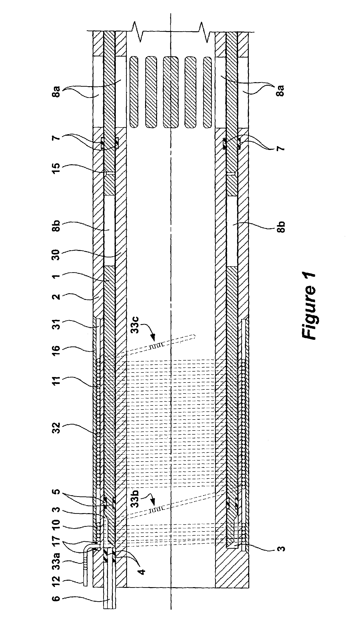
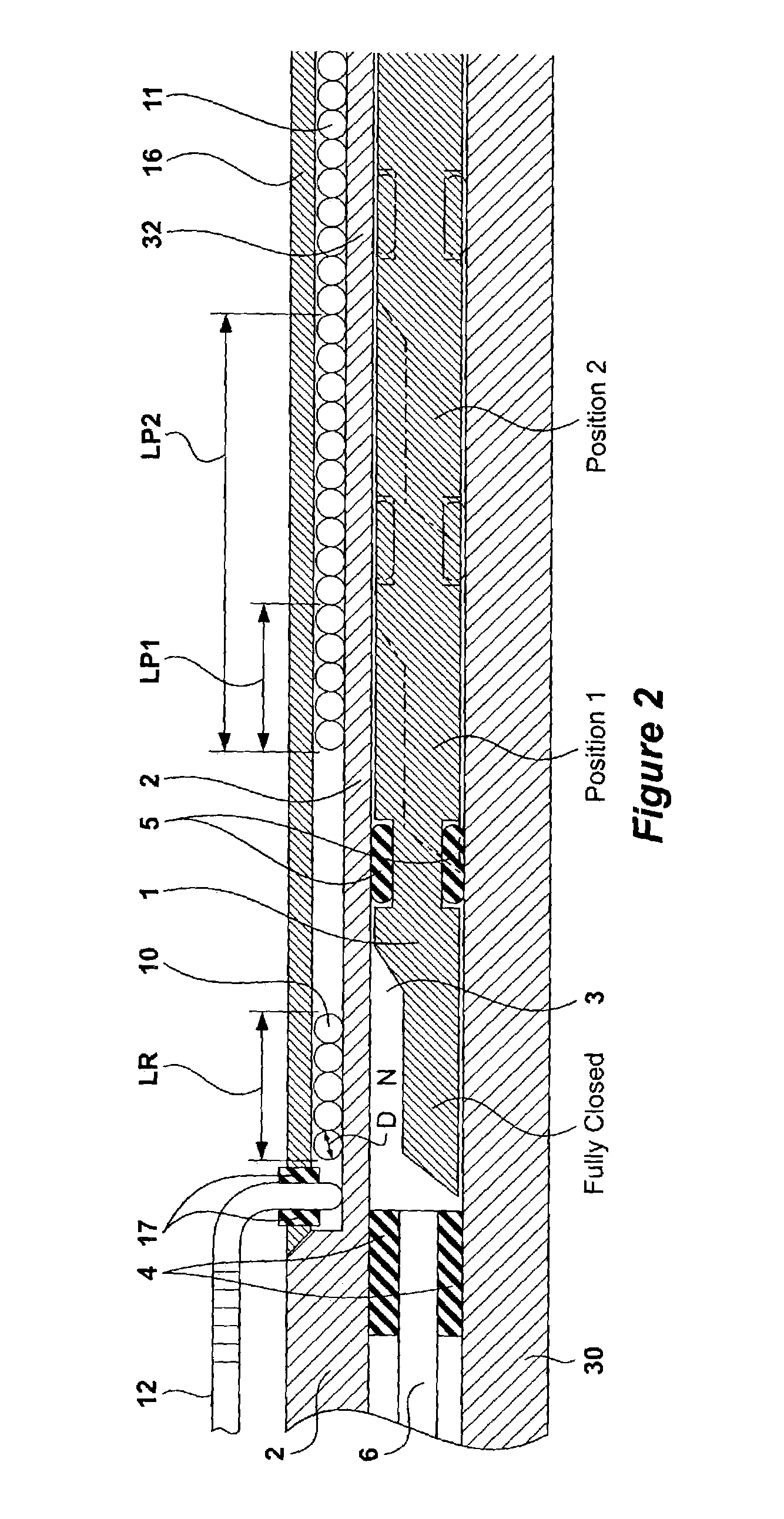
[0015]Referring to FIG. 1, a sliding sleeve 1 is positioned between a sleeve housing 2 and a production pipe 30. One skilled in the art will recognize that the housing 2 can be affixed to an otherwise standard section of production pipe 30, or may be integrally formed therewith as a single piece, i.e., as a special production tube section to be incorporated into the production string. Thus, as illustrated, the housing 2 and pipe 30 are integrated, but need not be so.

[0016]Within the housing 2 is a hydraulic cavity 3. The boundaries of the hydraulic cavity 3 are defined on one end by a sealable port 4, and on the other by one or more fluid-tight seal rings 5 (e.g. chevron seals) located on the sliding sleeve 1. Hydraulic fluid is forced into the hydraulic cavity 3 through a control line 6 that passes through the sealable port 4. Additional fluid tight seal rings 7 are located on the housing 2 to prevent hydrocarbons from entering the space between the sliding sleeve 1 and the housing...


PUM


Abstract

An apparatus and method for determining the position of a hydraulically actuated sliding sleeve valve in real time is disclosed. The apparatus comprises, in a preferred embodiment, a reference sensor and a position sensor, both of which constitute fiber optic windings wound around the hydraulic fluid cavity used to activate the sleeve. The sensors measure the pressure exerted by the hydraulic fluid in the cavity, with the reference sensor circumferentially lengthening to create an optical time delay indicative of the base line pressure of the hydraulic fluid. As the sleeve moves, the position sensor becomes increasingly exposed to the hydraulic fluid pressure and also begins to experience a time delay, which can be compared to the reference sensor's time delay to determine sleeve position.

Description

FIELD OF THE INVENTION[0001]This invention relates primarily to a sliding sleeve valve useful in conjunction with a production pipe used in oil / gas production.BACKGROUND OF THE INVENTION[0002]In hopes of producing oil and gas more efficiently, the petroleum industry continuously strives to improve its recovery systems. As such, those in the industry often drill horizontal, deviated, or multilateral wells, in which several wells are drilled from a main borehole. In such wells, the wellbore may pass through numerous hydrocarbon-bearing zones or may pass for an extended distance through one hydrocarbon-bearing zone. Perforating or “fracturing” the well in a number of different locations within these zones often improves production by increasing the flow of hydrocarbons into the well.[0003]In wells with multiple perforations, however, managing the reservoir becomes difficult. For example, in a well having multiple hydrocarbon-bearing zones of differing pressures, zones of high pressure ...

Claims


Application Information

Patent Timeline
IPC IPC(8): G01J1/04G01J1/42G01J5/08E21B34/14E21B47/06E21B47/12G01D5/353G01L11/02
CPCE21B34/14E21B47/06G01L11/025G01D5/35303E21B47/123E21B47/135
Inventor HAY, ARTHUR D.ROBINSON, ROBERTOGLE, PETER
Owner WEATHERFORD TECH HLDG LLC
Why Eureka
Try Eureka