Method of controlling the commutation in an electronically commutated motor, and an electronically commutated motor for carrying out said method

a technology of electronic commutation and electronic commutation, which is applied in the direction of synchronous motor starters, dynamo-electric machines, starter arrangements, etc., to achieve the effects of smooth motor operation, quiet operation, and improvement in efficiency

Inactive Publication Date: 2006-02-07
EBM PAPST ST GEORGEN & -
View PDF21 Cites 24 Cited by
  • Summary
  • Abstract
  • Description
  • Claims
  • Application Information

AI Technical Summary

Benefits of technology

[0005]According to the invention, this object is achieved by modifying the current limit value according to the ratio W / T, as explained below. The result of such a method is that current limiting is modified in load-dependent fashion, so that the upper current limit is lower at low rotation speeds, when the motor requires little power, than at high rotation speeds. The amplitude of the current pulses that flow through the stator at low rotation speeds is thereby automatically reduced, and the block length of those pulses is automatically increased by the rotation speed controller to compensate; this causes the motor to run more quietly, and can also bring about an improvement in efficiency.
[0006]Another means of achieving the stated object is to control the ON / OFF switching of the winding current using a first control signal and to control the shape of the current using a second control signal. A method of this kind allows the shape of the stator current pulses to be actively influenced, and quiet, smooth motor operation can thereby be achieved.

Problems solved by technology

The result of such a method is that current limiting is modified in load-dependent fashion, so that the upper current limit is lower at low rotation speeds, when the motor requires little power, than at high rotation speeds.

Method used


Image

  • Method of controlling the commutation in an electronically commutated motor, and an electronically commutated motor for carrying out said method
  • Method of controlling the commutation in an electronically commutated motor, and an electronically commutated motor for carrying out said method
  • Method of controlling the commutation in an electronically commutated motor, and an electronically commutated motor for carrying out said method

Examples


Embodiment Construction

[0020]In the Figures that follow, identical or identically functioning parts are in each case labeled with the same reference characters and usually are described only once. This applies in particular to the identical components in FIGS. 4 and 6.

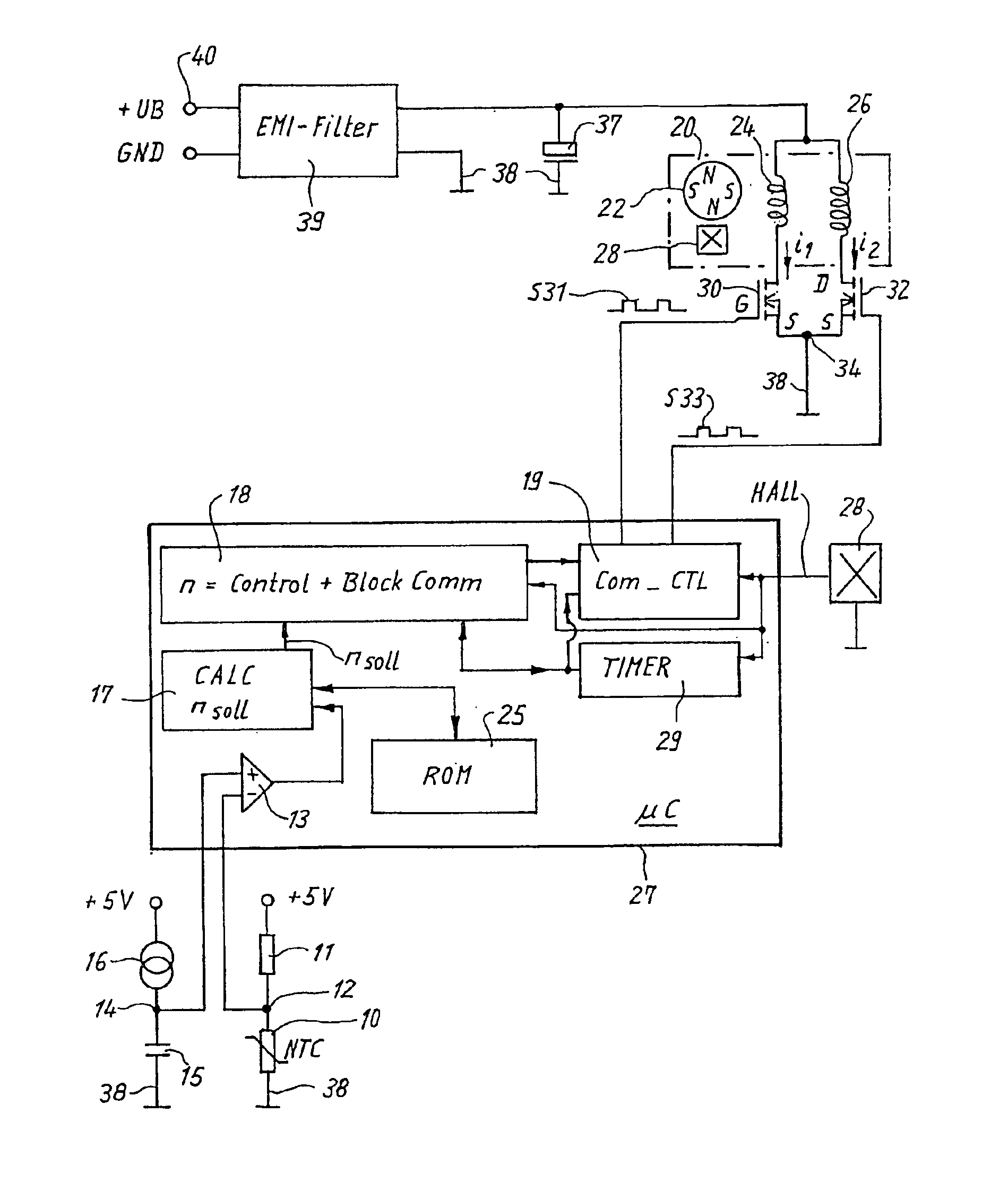
[0021]FIG. 1 is an overview diagram of an electronically commutated motor (ECM) 20, known in terms of its fundamental configuration from EP 0 657 989 B1 and corresponding U.S. Pat. No. 5,845,045, JESKE et al. (Assignee docket no. EP-3008). It can serve, for example, to drive a fan whose rotation speed is controlled by a temperature-dependent Negative Temperature Coefficient (NTC) resistor 10 which is connected, in series with a resistor 11, to a constant voltage of 5 V. Connecting point 12 of resistors 10, 11 is connected to the negative input of a comparator 13 whose positive input is connected to a node 14 that is connected via a capacitor 15 to ground 38 and via a constant-current member 16 to +5 V. When the temperature of NTC resistor 10...


PUM


Abstract

A method is disclosed for controlling the commutation in an electronically commutated motor (20) which comprises a stator having at least one phase (24, 26), and a permanent-magnet rotor (22), and with which a current limiter (36, 58) and a controller (18) for regulating a motor variable are associated. The current limiter (36, 58) serves to limit the current (I) in the at least one phase (24, 26) to a setpoint value. The regulation by means of the controller (18) is accomplished by modifying the distance in time (W) between switching on (t1) and switching off (t2) of the current (i1, i2) in the at least one phase. In this method, the setpoint value to which the current limiter limits the current (i1, i2) in the relevant phase is modifiable. It is modified substantially as a function of a ratio of two times (W/T), namely as a function of the ratio of the distance in time (W) between switching on (t1) and switching off (t2) of the current (i1, i2) in the relevant phase (24, 26) to the time period (T) required by the rotor, at the instantaneous rotation speed, to rotate through a specified rotation angle. A decrease in noise at low rotation speeds is thereby made possible.

Description

FIELD OF THE INVENTION[0001]The invention concerns a method of controlling the commutation in an electronically commutated motor (ECM), and an ECM for carrying out such a method.BACKGROUND[0002]EP 1 107 441 A2 and corresponding U.S. Pat. No. 6,396,226, SCHMIDER & LUKENICH, disclose an ECM in which an arrangement for current limiting is provided. Current limiting is important in particular upon startup of a motor, since when a motor's rotation speed is low, the voltage induced in its stator winding by the permanent-magnet rotor—the so-called counter-EMF—is also low; at startup, this can result in high currents which are substantially greater than the rated current of such a motor. If no current limiter is provided, the magnitude of the current spikes upon startup is limited only by the winding resistance and by the magnitude of the counter-EMF (which is low at low rotation speeds). These high currents result in corresponding motor noise, which is present in the audible range and whos...

Claims


Application Information

Patent Timeline
Patent Type & Authority Patents(United States)
IPC IPC(8): H02P7/00H02P6/00H02P6/20H02P6/28
CPCH02P6/20H02P6/002H02P6/28
Inventor BERROTH, HANSJORGVON DER HEYDT, THOMASJESKE, FRANKKUNER, ARNOLDLAYES, PAULSCHONDELMAIER, HANS-DIETERSTRASSER, GUNTHER
Owner EBM PAPST ST GEORGEN & -
Why Eureka
Try Eureka