Apparatus for recording optical information

a technology for optical information and recording apparatus, applied in the direction of optical beam source, head disposition/mounting, instruments, etc., can solve the problems of difficult random access, difficult high-density recording, and difficult to perform high-accuracy positioning

Inactive Publication Date: 2006-02-07
OPTWARE
View PDF51 Cites 50 Cited by
  • Summary
  • Abstract
  • Description
  • Claims
  • Application Information

AI Technical Summary

Benefits of technology

[0012]The present invention has been conceived taking such problems into consideration, and it is a first object of the invention to provide an apparatus and a method for recording optical information capable of performing multiplex recording of information in an optical information recording medium in whic...

Problems solved by technology

In general, holographic recording for recording information in a recording medium utilizing holography is performed by overlapping light carrying image information and reference light in a recording medium and writing resultant interference fringes in the recording medium.
In the configuration shown in FIG. 75, however, since the hologram recording medium 100 itself carries no information for positioning, there is only a mechanical way to position the information light 102 and reference light 104 on the hologram recording medium 100, which makes it difficult to perform the positioning with high accuracy.
This has resulted in problems in that removability (the ease of performing recording and reproduction of a hologram recording medium on a recording/reproducing apparatus after moving it from another recording/reproducing apparatus with the same results as on the previo...

Method used


Image

  • Apparatus for recording optical information
  • Apparatus for recording optical information
  • Apparatus for recording optical information

Examples


Embodiment Construction

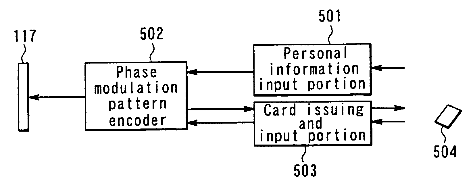
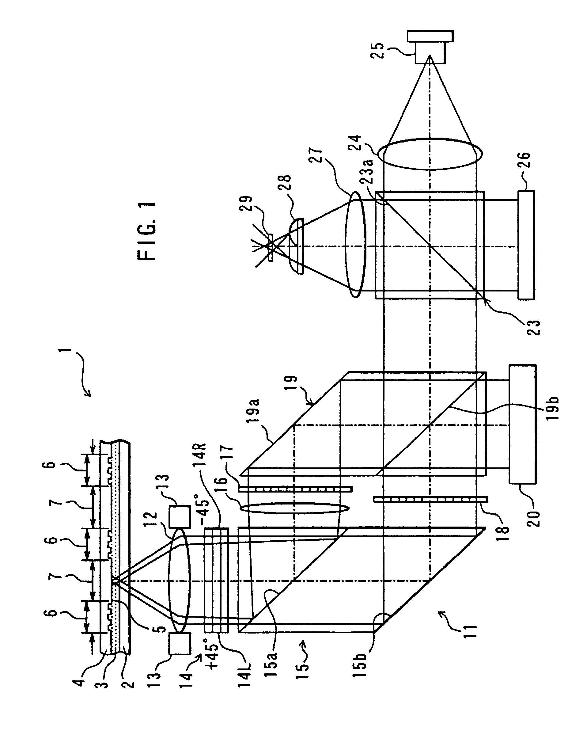
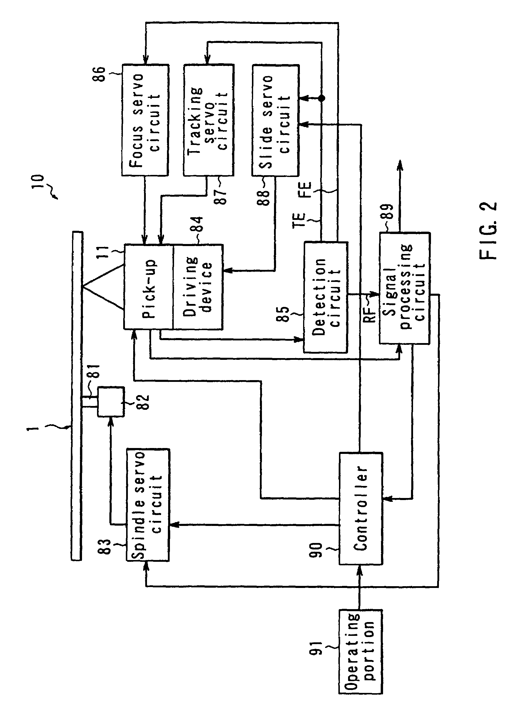
[0118]Embodiments of the present invention will now be described in detail with reference to the drawings. A first embodiment of the invention is an example in which multiplex recording is realized using phase encoding multiplexing. FIG. 1 is an illustration showing a configuration of a pick-up of an optical information recording / reproducing apparatus as an optical information recording apparatus and an optical information reproducing apparatus according to the present embodiment and a configuration of an optical information recording medium according to the present embodiment. FIG. 2 is a block diagram of a general configuration of the optical information recording / reproducing apparatus according to the present embodiment.

[0119]First, the configuration of the optical information recording medium according to the present embodiment will be described with reference to FIG. 1. The optical information recording medium 1 is configured by forming: a hologram layer 3 as an information rec...


PUM


Abstract

The present invention makes it possible to reduce the size of an optical system for multiplex recording or reproduction of information utilizing holography.
A pick-up (11) of an optical information recording/reproducing apparatus generates information light by spatially modulating laser light emitted by a light source device (25) with a spatial light modulator (18) depending on the information to be recorded and generates reference light for recording having a spatially modulated phase by spatially modulating the phase of laser beam emitted by the light source device (25) with a phase-spatial light modulator (17). The information light and the reference light for recording are projected upon an optical information recording medium (1) such that they converge in different positions, and information is recorded in the hologram layer (3) in the form of an interference pattern as a result of interference between the information light reflected by a reflecting film (5) and the reference light for recording. The positioning of the information light and the reference light for recording is carried out based on information recorded in address servo areas (6).

Description

[0001]This is a Continuation of application Ser. No. 09 / 601,702 filed Aug. 4, 2000, which in turn is a National Stage of PCT / JP99 / 00896, filed Feb. 26, 1999. The entire disclosure of the prior application(s) is hereby incorporated by reference herein in its entirety.TECHNICAL FIELD[0002]The present invention relates to an optical information recording apparatus and a method for the same for recording information in an optical information recording medium utilizing holography, an optical information reproducing apparatus and a method for the same for reproducing information from an optical information recording medium utilizing holography, an optical information recording / reproducing apparatus for recording information in an optical information recording medium and reproducing information from an optical information recording medium utilizing holography and an optical information recording medium in which information is recorded utilizing holography.BACKGROUND ART[0003]In general, ho...

Claims


Application Information

Patent Timeline
IPC IPC(8): G03H1/00G11B7/0065G11B7/007G11B7/085G11B7/09G11B7/125G11B7/135G11B7/14G11B7/24G11B7/24038
CPCG11B7/0065G11B7/00745G11B7/00781G11B7/085G11B7/08582G11B7/0938G11B7/127G11B7/128G11B7/1356G11B7/1365G11B7/14G11B7/24G03H1/12G03H1/0465G11B2007/0013G03H2001/0415G03H2001/267G03H2001/2675G03H2210/54G03H2250/42G11B7/24038G11B7/24044G11B7/08G11B7/24041G03H2210/12G11B2220/2537
Inventor HORIMAI, HIDEYOSHI
Owner OPTWARE
Why Eureka
Try Eureka